background image

– 6 –

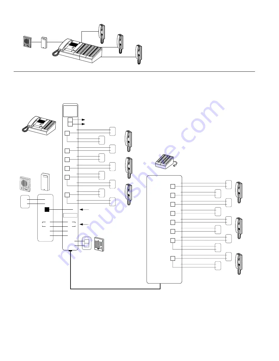
TC-10M single-master with TC-(20,40)G add-on selector

TC-10M

IF-DA

TB-AD1

TB-SE

TC-20G

IF-DA

TB-AD1

E

1
2

1
2

E

1
2

E

1
2

E

1
2

E

1
2

1
2

E

1
2

1
2

1

2

3

4

5

6

7

8

9

10

N

1
2

1
2

+ 
− 

R

T

12V

12V

+ 
− 

T

Sub station

TB-SE

Door adaptor

11

12

13

14

15

16

17

18

E

1

19

Add-on selector

TC-20G

R

1
2

E

2

1
2

E

3

1
2

E

4

1
2

E

5

1
2

E

6

1
2

E

7

1
2

8

1
2

E

9

1
2

10

1
2

TB-SE

Sub station

TC-10M

Master station

S

S

Connector

To: power supply

Do not connect any 
power source here.

★ 

IN

AC 15-16V

or DC18V

12V OUT

Designate any # terminal
for TB-AD1

20

Call extension
IER-2

(one per TC-M)

1

E

TC-M master, with a TC-G add-on selector,
expands its capacity up to 60 substations.
Choose the master and add-on selector to
meet your system's requirements.

Up to 3 TB-AD1 door station adaptors per TC-M.
5 wires homerun to TC-M.

Содержание Tc-10m

Страница 1: ...r SA 1 is available from Aiphone 1 Do not connect any power source other than specified on TC M master Fire or damage to the unit could result 2 Do not open TC M master High voltage is present inside...

Страница 2: ...g relay TAR 3 IF DA TC 10M TC 20M TC 20G TC 40G TB SE TB SE R IER 2 TAR 3 TB AD1 TB AD10 IF DA PS 18C PS 18E 10 call master 20 call master 20 call add on selector 40 call add on selector Handset sub s...

Страница 3: ...ide of master Features TC 20G or TC 40G add on selector connects additional TB SE subs allowing system expansion One or dual master configuration TB AD1 adaptor connects TC M with an IE IF Series audi...

Страница 4: ...om TB SE terminal 2 2 wires from TB SE subs must not be made common at any other point than on the TC M terminal block 1 12V 2 3 4 5 6 7 8 9 10 E E E E E E C M R R T T S S 1 12V 2 3 4 5 6 7 8 9 10 E E...

Страница 5: ...sub s station number numbered from the top on each 10 button row 2 parallel wires per TB SE sub nonpolarized Be sure to run each pair of wires directly to TC M master E line in each pair should not be...

Страница 6: ...3 1 2 E 4 1 2 E 5 1 2 E 6 1 2 E 7 1 2 8 1 2 E 9 1 2 10 1 2 TB SE Sub station TC 10M Master station S S Connector To power supply Do not connect any power source here IN AC 15 16V or DC18V 12V OUT Desi...

Страница 7: ...D6 1 2 E D7 1 2 D8 1 2 E D9 1 2 D10 1 2 IF DA E 1 2 E 1 2 E 1 2 E 1 2 E 1 2 E 1 2 E 1 2 E 1 2 1 2 1 2 3 4 5 6 7 8 9 10 12V T R S S To power supply Do not connect any power source here IN AC 15 16V or...

Страница 8: ...larized To power supply Do not connect any power source Designate any terminal for TB AD1 Call extension IER 2 1 E Call extension IER 2 1 E Common TB SE sub rings two TC M Masters Each master can call...

Страница 9: ...zer is activated and on TB SE sub call tone sounds at reduced volume TAR 3 relay activates an AC operated buzzer AC 240V 0 3A DC operated buzzer must be mechanical type DC 24V 1 0A Do not use DC elect...

Страница 10: ...ll TC M leaves sub A waiting pressing a sub B select button When sub B picks up the call sub A hears a busy tone TC M depresses Transfer switch TC M then reselects waiting sub A with red LED on Three...

Страница 11: ...eive and call tone volume Upper control adjusts handset receiver volume when TC M does not hear a TB SE sub clearly Tone control adjusts ringing tremolo 3 levels TC M dual master system Two masters ca...

Страница 12: ...be responsible for any costs incurred involving on site service calls 8 8 SPECIFICATIONS Power source DC18V 350mA max or AC 15 16V 50 60Hz 750mA max Power consumption 6W max 3W standby Capacity 60 sta...

Отзывы: