October 2006
-
13
-
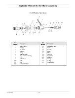
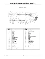
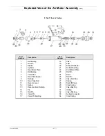
Disassembly and Reassembly of the Angle Head Section
Disassembly
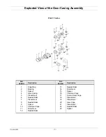
1. Loosen and remove the Angle Head Casing Cover, Driven Gear, and Driven Gear Spindle.
2. Loosen Locking Nut from the Clutch Casing and remove the Angle Head Casing.
3. Remove the Bearing from down inside the Angle Head Casing and remove the Driving Gear.
4. Thoroughly clean all parts.
Inspection
1. Inspect the Driven and Driving Gears for pitting and grooving.
2. Inspect all Bearings for side play and knocking.
3. Inspect the Driven Gear Spindle for side wear.
4. Replace all worn parts.
Assembly
1. Set the Driven Gear into the Angle Head Casing Cover and install the Balls around the Driven Gear.
2. Install the Driven Gear into the Angle Head Casing and secure by threading the Angle Head Casing Cover
into the Angle Head Casing.
3. Put a small amount of grease on the Driving Gear and install it into the Angle Head Casing.
4. Install the Adjusting Spacer and Bearing into the Angle Head Casing.
Note:
The Adjusting Spacer is used
to set the gear lash.
5. Install the Angle Head Casing onto the Clutch Casing and test the tool.
Содержание Lite-Touch Series
Страница 2: ......


