background image

13

Gen IV Controller with Smart Arm Setup Instruction Manual

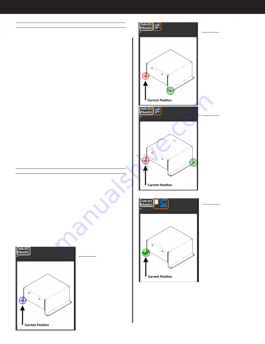
Image 5

Job Seq 2 is selected. 

Arm is in position 

1 (shown in red as 

incorrect position) and 

screen shows green 

target highlighting 

fastener to be 

inserted. Stopped icon 

appears showing that 

the tool is disabled.

Image 6

Job Seq 3 is selected. 

Arm is in position 

1 (shown in red as 

incorrect position) 

and screen shows 

green target 

highlighting fastener 

to be inserted. 

Stopped icon 

appears showing that 

the tool is disabled.

Image 7

First fastener has been 

inserted successfully. 

Current position is 

marked OK. Status 

bar shows 'Job 

Sequence Complete' 

and 'Location 

Complete'.

9.2.4  External Control

Line side control can be used to command which 

fastener needs to be run. Select the Job that 

matches the work type (initial or rework) and 

select the job sequence number that is tied to the 

fastener location. Configure the assignable IO for 

the required interface type (CC-Link, Anybus, etc.) 

to select a job number and job sequence number. 

Refer to the white paper for the specific interface for 

configuration details.

In this example, selecting Job 1 and Job Sequence 

2 will select PSet 2 and disable the controller until the 

arm is in the correct position for fastener 2.

Selecting Job 2 and Job Sequence 3 will select PSet 

6 and disable the controller until the arm is in the 

correct position for fastener 3.

The front panel and physical IO can be used to 

select job number, sequence number, and reset 

job if needed for testing. The job can be changed 

by holding the toggle button and pressing an up/

down button. Job sequence can be changed by 

just pressing an up or down button when jobs are 

enabled.

9.2.5  Add Image for Runscreen

Add the image and three locations as shown in "9.1 

Example 1" on page 9.

9.2.5.1  Runscreen Behavior

Return to the Gen IV Runscreen and navigate to 

the screen with the part image. The image will 

now direct the user to fasten the bolt that is being 

commanded from the ‘Select Job Sequence’ input.

The next images show what happens when the 

Arm is over location 1 but the commanded Job 

Sequence from IO changes from 1, 2, and then 3.

Image 4

Job Seq 1 is selected. 

Arm is in correct 

position.

Содержание AcraDyne

Страница 1: ...Gen IV Controller with Smart Arm Setup Instruction Manual 10000 SE Pine St Portland OR 97216 800 852 1368 503 254 6600 Fax 800 582 9015 www aimco global com ...

Страница 2: ...et Setup 12 9 2 2 Job Setup 12 9 2 3 Accessory Setup 12 9 2 4 External Control 13 9 2 5 Add Image for Runscreen 13 9 2 6 Clearing locations 14 10 Adding a Proximity or Limit Switch 14 11 Icon Reference 14 12 References 14 Table of Contents 1 Introduction The Smart Arm Accessory allows an articulated arm with encoders to be used with the Gen IV controller Fastener locations can be programmed into t...

Страница 3: ... steps of the setup are 1 Make all hardware connections 2 Power on the Smart Arm Accessory and Gen IV Controller 3 Configure the accessory IP settings from the controller 4 Add the Smart Arm accessory in the Gen IV controller settings 5 Configure the accessory settings and add arm locations 6 Add runscreen image if required Image must be 470 x 550 pixels for best fit to controller screen 7 Configu...

Страница 4: ...le the controller if the arm is positioned over a fastener that is part of has already been completed The locations on the screen will reset when the job is complete or the Job Complete IO is triggered This system also allows more flexibility with PSet choice If a set of fastenings have different torque angle requirements depending on if the part is new or being reworked then the job can be change...

Страница 5: ...ed PSet from the location configuration Select Job Sequence This will pair a location to a job sequence The controller will select a specific job sequence when the location is matched Verify job Sequence The tool will be disabled until the correct job sequence is selected that matches the job sequence from the location configuration 7 3 Accessory Scanning and IP Setup Screen This screen is used to...

Страница 6: ...en added Part Images This section allows you to add edit or delete custom images for the Smart Arm Runscreen See instructions in 8 Smart Arm Runscreen on page 7 Encoder Positions List of saved smart arm locations See following section for instructions on setting up locations 7 5 Encoder Position Setup To begin setting up encoder positions start by homing the arm position 7 5 1 Homing Pressing the ...

Страница 7: ...the encoders and use it as the target Use this to easily add a location by positioning the tool on the bolt and clicking Use Current Position Click OK at the bottom of the screen and this location will be added to the list 8 Smart Arm Runscreen Uploading a custom image allows you to visualize the fastening locations of your project on the Smart Arm Runscreen This feature was added in SYSREL 3R18 A...

Страница 8: ...ed Click again to return to Jobs screen 8 2 Associate an Image with a Job Once a smart arm accessory and part images have been set up you can associate a job with a specific smart arm part image in the controller s Job interface This image will automatically appear when that job is chosen From the Main Gen IV Controller Screen select Job The jobs screen will appear Select the job that you want to ...

Страница 9: ... over valid encoder values 9 1 Example 1 Select PSets Based on Location This example shows how to set up the most basic control option Three locations will be programmed in the controller so that the controller will enable the tool and select a specific PSet when the tool is located over a fastener 9 1 1 PSet Setup Create three PSets These can be named in the advanced settings to make it more clea...

Страница 10: ...location Before adding locations be sure to move the arm to the home position and press the Home button on the accessory box This will be the reference position for all added locations Add three fastener locations Click the Add button to add a new location Move the tool onto the first fastener The encoder values in the Current column will update with the encoder counts for this position Click Use ...

Страница 11: ...screen Any positions marked as complete will be reset 9 2 Example 2 Command Bolt Locations via External Source This example shows how to set up a more complex control scheme This application will have the following requirements Three fasteners Each fastener has two unique tightening specifications Initial work Re work This application will use jobs to select the work type initial or rework and the...

Страница 12: ...ns encoder values Click OK Check Repeat this for location 2 and 3 Set Parameter to 2 for location 2 and 3 for location 3 Click OK Check until all Smart Arm configurations are saved Each location is now paired with a job sequence number Now configure the line side control to select the job and job sequence paired to the fastener and the tool will not be enabled until the tool is located over the co...

Страница 13: ...number Refer to the white paper for the specific interface for configuration details In this example selecting Job 1 and Job Sequence 2 will select PSet 2 and disable the controller until the arm is in the correct position for fastener 2 Selecting Job 2 and Job Sequence 3 will select PSet 6 and disable the controller until the arm is in the correct position for fastener 3 The front panel and physi...

Страница 14: ... incorrect IP settings in the controller or accessory SARM will show on the top LED display 12 References 30887 Smart Arm Assembly Encoder Kubler 8 3620 525E 2048 30860 Smart Arm Accessory Encoder Interface Image 8 All fasteners inserted Tool is disabled Status bar shows job complete Reset job to start new part For a description of icons see Icon Reference on page 11 9 2 6 Clearing locations The R...

Страница 15: ......

Страница 16: ...EXICO SA DE CV 10000 SE Pine Street Ave Cristobal Colon 14529 Portland Oregon 97216 Chihuahua Chihuahua 31125 Phone 503 254 6600 Mexico Toll Free 1 800 852 1368 Phone 01 614 380 1010 Fax 01 614 380 1019 LIT MAN275 Rev 07 26 22 Printed in USA 2022 AIMCO ...

Отзывы: