ii
SAFETY INSTRUCTIONS
• Before getting started, please read the following important cautions:
• All cautions and warnings on the equipment or in the manuals should be
noted.
• Most electronic components are sensitive to electrical static discharge.
Therefore, be sure to ground yourself at all times when installing the
internal components.
• Use a grounding wrist strap and place all electronic components in
static-shielded devices. Grounding wrist straps can be purchased in any
electronic supply store.
• Be sure to turn off the power and then disconnect the power cords from
your system before performing any installation or servicing. A sudden
surge of power could damage sensitive electronic components.
• Do not open the system’s top cover. If opening the cover for
maintenance is a must, only a trained technician should do so.
Integrated circuits on computer boards are sensitive to static electricity.
Before handling a board or integrated circuit, touch an unpainted
portion of the system unit chassis for a few seconds. This will help to
discharge any static electricity on your body.
• Place this equipment on a stable surface when install. A drop or fall
could cause injury.
• Please keep this equipment away from humidity.
• Carefully mount the equipment into the rack, in such manner, that it
won’t be hazardous due to uneven mechanical loading.
• This equipment is to be installed for operation in an environment with
maximum ambient temperature below 35°C.
• The openings on the enclosure are for air convection to protect the
equipment from overheating. DO NOT COVER THE OPENINGS.
•
Never pour any liquid into ventilation openings. This could cause fire or
electrical shock.
• Make sure the voltage of the power source is within the specification
on the label when connecting the equipment to the power outlet. The
current load and output power of loads shall be within the specification.
• This equipment must be connected to reliable grounding before using.
Pay special attention to power supplied other than direct connections,
e.g. using of power strips.
• Place the power cord out of the way of foot traffic. Do not place
anything over the power cord. The power cord must be rated for the
Содержание SB122-PH
Страница 1: ...SB122 PH Storage Server Barebone User s Manual UM_SB122 PH_v 2_122215...
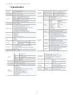
Страница 9: ...2 Chapter 1 Product Introduction 1 2 Specifications...
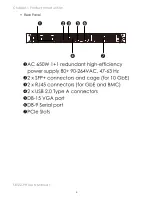
Страница 11: ...4 SB122 PH User s Manual Chapter 1 Product Introduction Rear Panel...
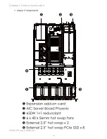
Страница 12: ...5 Chapter 1 Product Introduction SB122 PH User s Manual Major Components...
Страница 37: ...30 Chapter 3 Motherboard Setting SB122 PH User s Manual 3 2 Motherboard block diagram...
Страница 38: ...31 Chapter 3 Motherboard Setting SB122 PH User s Manual 3 3 Motherboard Content List...
Страница 39: ...32 Chapter 3 Motherboard Setting SB122 PH User s Manual 3 4 Internal Connectors Jumpers...
Страница 40: ...33 Chapter 3 Motherboard Setting SB122 PH User s Manual...
Страница 41: ...34 Chapter 3 Motherboard Setting SB122 PH User s Manual...
Страница 42: ...35 Chapter 3 Motherboard Setting SB122 PH User s Manual...
Страница 43: ...36 Chapter 3 Motherboard Setting SB122 PH User s Manual...
Страница 44: ...37 Chapter 3 Motherboard Setting SB122 PH User s Manual...
Страница 45: ...38 Chapter 3 Motherboard Setting SB122 PH User s Manual...
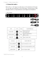
Страница 46: ...39 Chapter 3 Motherboard Setting SB122 PH User s Manual 3 5 LEDs 3 5 1 Front Panel LED...
Страница 47: ...40 Chapter 3 Motherboard Setting SB122 PH User s Manual 3 5 2 Rear Panel LED...
Страница 48: ...41 Chapter 3 Motherboard Setting SB122 PH User s Manual 3 5 3 Internal LEDs...
Страница 54: ...Chapter 5 BMC Configuration and Settings SB122 PH User s Manual 2 Input IP address Set static IP...
Страница 55: ...Chapter 5 BMC Configuration and Settings SB122 PH User s Manual 3 Input subnet mask address...
Страница 66: ...Chapter 6 Hardware Introduction SB122 PH User s Manual 6 2 RISER CARD HARDWARE INTRODUCTION 6 2 1 Riser Card...
Страница 68: ...Chapter 6 Hardware Introduction SB122 PH User s Manual 6 2 3 Internal Connectors Jumpers Power Connector J1...
Страница 69: ...Chapter 6 Hardware Introduction SB122 PH User s Manual 6 3 Drive Slot Map...

