SISTEMI DI SICUREZZA
5
SAFETY SYSTEMS
FL - FP - FA
5-7
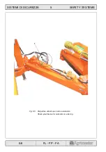
Dispositivo antiurto per rientro automatico
(Fig. 5-5):
La trinciatrice è equipaggiata con una valvola (montata
sul martinetto del parallelogramma) al fine di permet-
terne il rientro automatico quando incontra una forte
resistenza da parte del prodotto da trinciare.
Regolazione:
Personale richiesto: 1 OPERATORE
In caso di necessità, per eseguire la regolazione della
valvola procedere nel modo seguente:
• Arrestare la trinciatrice disinserendo la presa di
forza della trattrice ed attendere che il rotore sia
completamente fermo.
QUANDO SI DISINSERISCE LA PRESA DI FORZA
DELLA TRATTRICE, L’ALBERO CARDANICO
SMETTE DI RUOTARE MA CIÒ NON SIGNIFICA
CHE IL ROTORE SIA COMPLETAMENTE FERMO,
POICHÈ ALL’INTERNO DELLA SCATOLA INGRA-
NAGGI DELLA TRINCIATRICE È PRESENTE IL
DISPOSITIVO DI RUOTA LIBERA.
• Svitare (nel caso in cui la trinciatrice non dovesse
rientrare) o avvitare (nel caso in cui la trinciatrice
dovesse rientrare troppo facilmente) la vite 1 di un
quarto di giro per volta.
PERICOLO !
Shock-proof device for automatic re-entering
(Fig. 5-5):
The shredder is provided with a valve (mounted on the
jack of the parallelogram) in order to allow the auto-
matic re-entering when the product that has to be
shredded creates a strong resistance.
Adjustment:
Required staff: 1 OPERATOR
If necessary, follow the under-mentioned indications in
order to adjust the valve:
• Stop the shredder disconnecting the PTO of the
tractor and wait until the rotor is perfectly motion-
less.
WHEN YOU DISCONNECT THE PTO OF THE
TRACTOR, THE CARDAN SHAFT STOPS ROTAT-
ING, BUT THIS DOES NOT MEAN THAT THE
ROTOR IS PERFECTLY MOTIONLESS, SINCE INTO
THE GEARBOX OF THE TRACTOR THERE IS THE
FREE WHEEL DEVICE.
• Unscrew (if the shredder does not re-enter) or screw
(if the shredder re-enters too easily) the screw 1 of a
quarter of a turn at a time.
DANGER !
Содержание FA 150
Страница 8: ...AVVERTENZE 0 WARNINGS 0 4 FL FP FA Fig L Fig M Fig N L M N ...
Страница 16: ...CARATTERISTICHE 2 SPECIFICATIONS 2 4 FL FP FA 1 2 3 4 5 6 ...
Страница 18: ...CARATTERISTICHE 2 SPECIFICATIONS 2 6 FL FP FA 5 4 7 1 2 3 6 8 ...
Страница 25: ...MOVIMENTAZIONE 3 MOVING 3 2 FL FP FA Fig 3 1 Sollevamento FL FP FA Lifting FL FP FA 1 2 3 4 ...
Страница 40: ...INSTALLAZIONE 4 INSTALLATION 4 12 FL FP FA Fig 4 12 ...
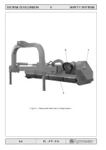
Страница 45: ...SISTEMI DI SICUREZZA 5 SAFETY SYSTEMS 5 4 FL FP FA Fig 5 4 Componenti di sicurezza Safety devices 1 3 2 ...
Страница 70: ...ACCESSORI 9 ACCESSORIES 9 4 FL FP FA Fig 9 3 Alette spargitrici Spreading vanes 1 ...
Страница 76: ...ACCESSORI 9 ACCESSORIES 9 10 FL FP FA Fig 9 7 Fissaggio distributore Distributor fixing ...

