INSTALLAZIONE
4
INSTALLATION
FL - FP - FA
4-5
4.1.2 Collegamento tre punti
Assicurarsi che la trinciatrice sia posizionata su di un
terreno piano.
Personale richiesto:
Primo collegamento - 1 TECNICO QUALIFICATO
Collegamenti successivi - 1 OPERATORE
Collegare i tre punti di fissaggio della trinciatrice alla
trattrice nel modo seguente:
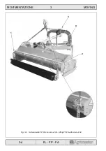
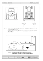
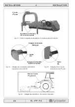
• Collegare i punti d’attacco (Fig. 4-3) ai bracci del
sollevatore della trattrice (Fig. 4-4).
• Collegare il terzo punto (Fig. 4-3) alla trattrice (Fig.
4-5).
Assicurarsi che i collegamenti dei tre punti alla
trattrice siano eseguiti correttamente. In particolar
modo le spine, dopo essere state inserite, devono
essere bloccate dalle copiglie di sicurezza (Fig. 4-4
e 4-5).
• Collegare i tubi dei martinetti agli attacchi presenti
sulla trattrice.
A collegamento avvenuto è necessario che i tubi:
• siano sufficientemente lunghi,
• non interferiscano con il sollevatore della trattrice,
• non interferiscano con l’albero cardanico,
• comandino sempre lo stesso movimento.
• Mettere in tensione il braccio terzo punto avvitan-
dolo (Fig. 4-6).
ATTENZIONE
NOTA
4.1.2 Three-point-hitch
Make sure that the shredder is positioned on a flat
ground.
Required staff:
First connection - 1 TRAINED TECHNICIAN.
Following connections - 1 OPERATOR.
Connect the three linkage points of the shredder to the
tractor as follows.
• Connect the connection point (Fig. 4-3) to the tractor
lift arms (Fig. 4-4).
• Connect the third point (Fig. 4-3) to the tractor (Fig.
4-5).
Make sure that the three points are properly con-
nected to the tractor. It is essential that the pins,
once they have been installed, are secured by
means of the safety pins (Fig. 4-4 and 4-5).
• Connect the hydraulic jacks pipes to the connec-
tions available on the tractor.
Once the pipes have been connected make sure that
they:
• are long enough,
• do not interfere with the tractor lift,
• do not interfere with the cardan shaft,
• always control the same movement.
• Tighten the third point arm (Fig. 4-6).
CAUTION
NOTE
Содержание FA 150
Страница 8: ...AVVERTENZE 0 WARNINGS 0 4 FL FP FA Fig L Fig M Fig N L M N ...
Страница 16: ...CARATTERISTICHE 2 SPECIFICATIONS 2 4 FL FP FA 1 2 3 4 5 6 ...
Страница 18: ...CARATTERISTICHE 2 SPECIFICATIONS 2 6 FL FP FA 5 4 7 1 2 3 6 8 ...
Страница 25: ...MOVIMENTAZIONE 3 MOVING 3 2 FL FP FA Fig 3 1 Sollevamento FL FP FA Lifting FL FP FA 1 2 3 4 ...
Страница 40: ...INSTALLAZIONE 4 INSTALLATION 4 12 FL FP FA Fig 4 12 ...
Страница 45: ...SISTEMI DI SICUREZZA 5 SAFETY SYSTEMS 5 4 FL FP FA Fig 5 4 Componenti di sicurezza Safety devices 1 3 2 ...
Страница 70: ...ACCESSORI 9 ACCESSORIES 9 4 FL FP FA Fig 9 3 Alette spargitrici Spreading vanes 1 ...
Страница 76: ...ACCESSORI 9 ACCESSORIES 9 10 FL FP FA Fig 9 7 Fissaggio distributore Distributor fixing ...

