19/09/18
Page 19 of 67
ASR650 Operational Manual
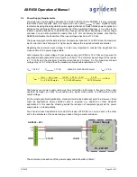
3.2.4
ST3
– Connector for 4/8-channel antenna multiplexer
Unlike for the ASR550, there is no additional adapter board required for connecting a 4-channel
or 8-channel antenna multiplexer. The electronics and the connector are on the ASR650 already.
Via the connector ST3, the multiplexers are supplied with power and it also provides the required
control lines for switching the antennas.
Pin Number
Function
1
Power supply for MUX
2
Control line A
3
Control line B
4
Control line C
5
GND
The control lines are also used for detecting the MUX-type during the initialization period
– so
please always connect all of them. The wiring to the external multiplexer boards is 1:1. There is
no special cable required here but the connection between reader and multiplexer should be kept
as short as possible.
3.3
Signalization
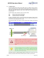
The ASR650 has three on-board LEDs which indicate the reader status. In general, the yellow
LED indicates that the reader is switched on and the Firmware is running, the green LED indicates
a successful tag read and the red LED means that there is a fault condition. The table below lists
the possible indications related to the operating conditions:
Yellow
(Power)
Green
(Read)
Red (Service)
Function
continuously on
off
off
Reader status OK
continuously on
flashing
off
Tag was read
flashing
off
off
Reader is OK and Sync. Slave
flashing
off
continuously on
Low input voltage (<11.0V DC)
continuously on
flashing
continuously on
Antenna fault
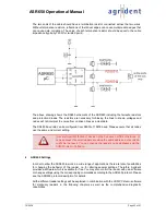
Condition one, two and three indicate that the reader is working properly. If the input voltage is
below 11.0 Volts DC, the reader will shut down the transmitter in order to avoid overheating. The
ASR650 will also disable the transmitter if the antenna inductance and / or the antenna impedance
are completely wrong. The antenna requirements are explained in chapter 2.1.6.


