NOTE
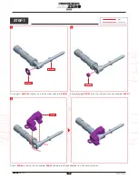
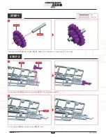
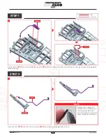
STEP 1
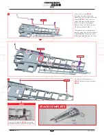
STEP 2
2
4
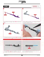
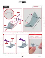
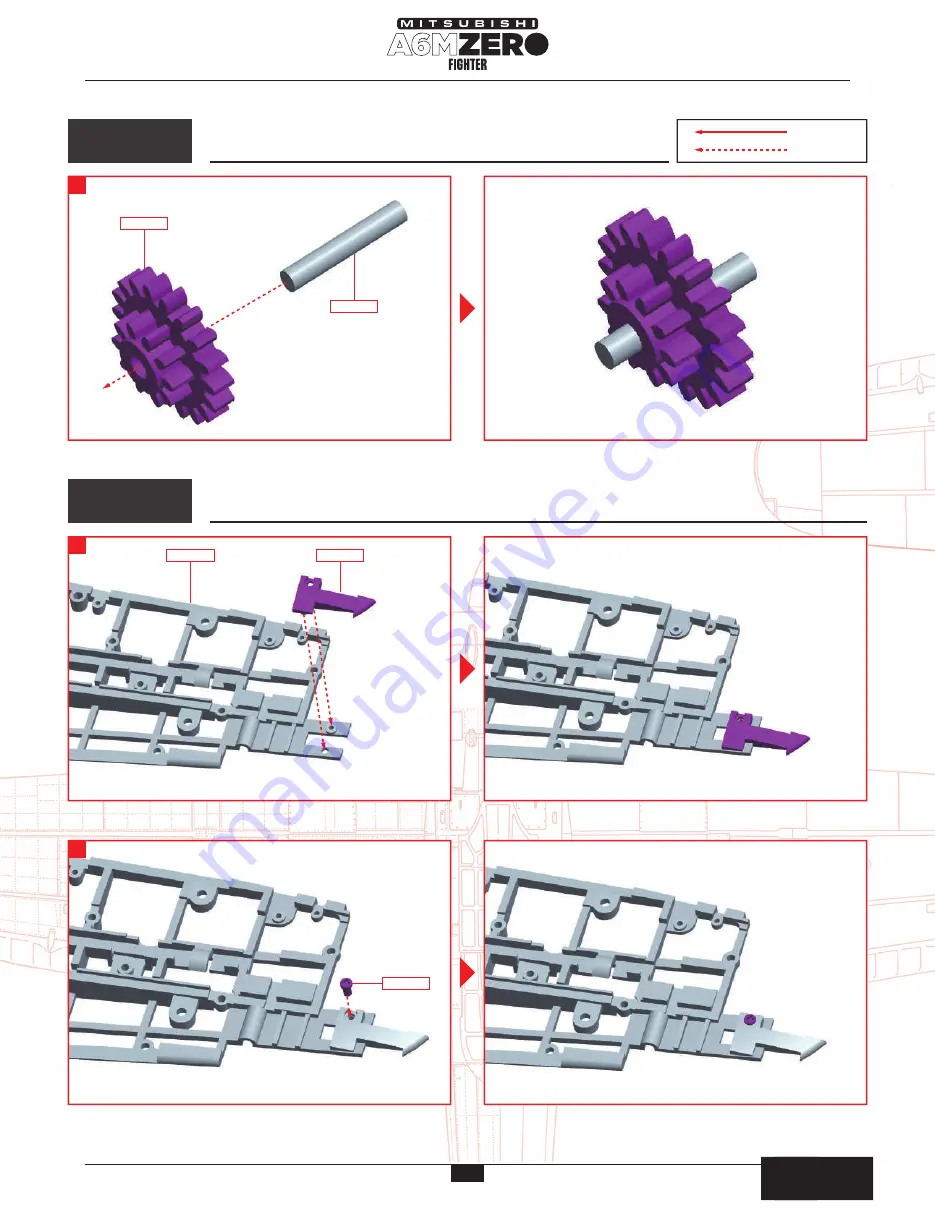
Insert the shaft
032-05
into the gear
032-03
. Keep it in a safe place until required in a later stage.
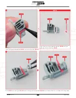
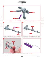
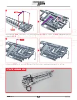
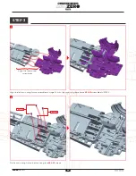
Pass the LED wire
032-04
through the wing frame and
insert the LED at the end into the
wing tip
032-02
. The wire runs
under the frame in four places,
shown circled in the diagram
below. Check that the wire runs
around any screw holes.
This process can also be done in
reverse, inserting the LED into the
wing tip before fixing the wire in
the correct positions on the wing.
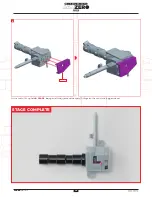
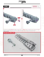
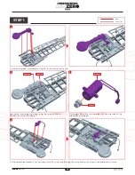
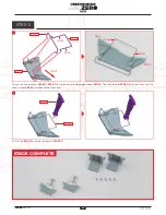
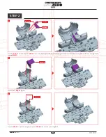
Fit the wing tip
031-02
onto the wing frame
032-01
that came wth stage 31.
Fix the wing tip
032-02
in place using a
032-07
screw.
032-05
032-03
032-02
032-04
LED board
LED board
032-07
032-07
031-01
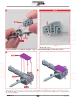
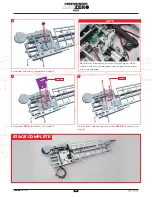
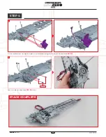
Fix the two LED boards on
032-04
in place using 2 x screws
032-07
.
1
1
3
The two LED boards
032-04
should be
attached with the writing facing upwards.
STAGE COMPLETE
:
Glue
:
Don’t Glue
組み立てガイド
組み立てガイド
24
AGORA
MODELS

