09
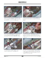
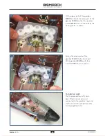
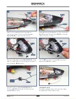
Completed work
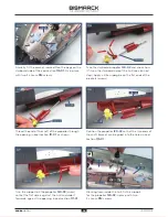
The two rudders and the motor have been
fitted to the stern of the model.
You may find that the fit of the motor is a bit wobbly.
This will be fixed in a later stage.
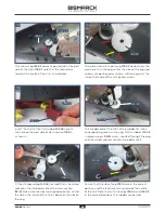
Fit the shaft of the second rudder
123-06
up into the
hole in the stern section
118-01
on the starboard side.
02
Fix the rudder
123-06
in place using a
PWM
screw,
inserted through the cog and the raised screw socket
and into the rudder shaft.
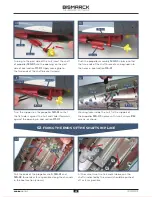
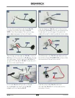
Wrap the cable label
123-07
(D1) round
the end of the cable from motor
123-01
near to the connector, as shown.
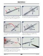
Fit the large cog
123-02
on the shaft of the
motor
123-01
. Make sure the side without
any teeth is positioned as shown (arrow).
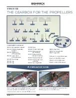
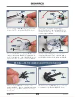
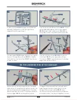
Ensure that the cogs
123-03
and
123-04
are positioned
as shown, with the rudders parallel. Identify the fixing
point for the motor
123-01
at the rear of part
118-01
. Fix
the motor in place with two
PWM
screws so that the
teeth of cog
123-02
interlock with the cogs
123-03
and
123-04
.
02
. FITTING THE MOTOR FOR THE RUDDER
01
03
123-06
118-01
123-06
123-04
123-01
123-07
123-01
123-03
PWM
123-01
123-02
123-02
123-04
118-01
10
PWM
PWM
29
28
AGORA
MODELS
29
AGORA
MODELS


