background image

U1253A Quick Start Guide

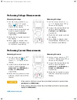
Performing Voltage Measurements

Performing Current Measurements
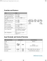
C A U T I O N

If the current is 

≤ 

440 mA, connect the red and black test leads to input terminals 

µA.mA (red)

 and 

COM (black).

If the current is > 440 mA, connect the red and black test leads to input terminals 

A (red)

 and 

COM (black)

.

Measuring AC voltage

1

Set the rotary switch to 

For 

 and 

 mode, 

press 

 to ensure 

 is 

shown on the display.

2

Connect the red and black test 
leads to input terminals 

V. mV (red)


and 

COM (black)


respectively.

3

Probe the test points and read 
the display.

4

Press 

 to display dual 

measurements. Parameter can 
be switched consecutively.

Measuring DC voltage

1

Set the rotary switch to 


or 

. Ensure that 

 is 

shown on the display. 

2

Connect the red and black test 
leads to input terminals 

V. mV (red)

 and 

COM (black)


respectively.

3

Probe the test points and read 
the display.

4

Press

 to display dual 

measurements. Parameter can 
be switched consecutively.

Measuring AC current

1

Set the rotary switch to 


or 

. Press 

 to 

ensure 

 is shown on the 

display.

2

Connect the red and black test 
leads to input terminals 

µA.mA (red)


and 

COM (black) 

or 

A (red)


and 

COM (black) 

respectively.

3

Probe the test points in series 
with the circuit and read the 
display.

Measuring DC current

1

Set the rotary switch to 


or 

. Ensure that 

 is 

shown on the display. 

2

Connect the red and black test 
leads to input terminals 

µA.mA (red)


and 

COM (black) 

or 

A (red)


and 

COM (black) 

respectively.

3

Probe the test points in series 
with the circuit and read the 
display.

U1253A QSG.fm  Page 2  Tuesday, September 23, 2008  9:44 AM

Содержание U1253A

Страница 1: ...n software and instrument drivers Rechargeable 7 2 V battery Power cord and AC adapter Certificate of Calibration If anything is missing or damaged please contact the nearest Agilent Sales Office WARNING Ensure the terminal connections are correct for that particular measurement selection before starting any measurement To avoid damage to the device do not exceed the input limit Agilent Technologi...

Страница 2: ... or Ensure that is shown on the display 2 Connect the red and black test leads to input terminals V mV red and COM black respectively 3 Probe the test points and read the display 4 Press to display dual measurements Parameter can be switched consecutively Measuring AC current 1 Set the rotary switch to or Press to ensure is shown on the display 2 Connect the red and black test leads to input termi...

Страница 3: ... Set the rotary switch to 2 Connect the red and black test leads to input terminals red and COM black respectively 3 Connect the red test lead to the positive terminal of the capacitor and the black test lead to the negative terminal 4 Read the display Temperature 1 Set the rotary switch to Press to select temperature measurement 2 Connect the red and black test leads to input terminals red and CO...

Страница 4: ...ill be shown on the display This accommodates a higher frequency range of up to 20 MHz 6 The signal is out of the U1253A frequency measurement range of 20 MHz if the reading is still unstable after Step 5 Square Wave Output 1 Turn the rotary switch to 2 Press to select duty cycle on the primary display 3 The default square wave frequency is 600 Hz as shown by the secondary display with a 50 duty c...

Страница 5: ... Turns on dual display Press Starts manual data logging Press and hold for 1 s Views the logged data Press for 1 s press or to scroll through the logged data Clears the logged data Press for 1 s press for 1 s Measurement Functions Input Terminal Overload Protection Voltage COM 1000 Vrms Diode 1000 Vrms 0 3 A short circuit current Resistance Capacitance Temperature Current μA and mA µA mA COM 440 m...

Страница 6: ...cated conditions are fully understood and met WARNING A WARNING notice denotes a hazard It calls atten tion to an operating procedure practice or the like that if not correctly performed or adhered to could result in personal injury or death Do not proceed beyond a WARNING notice until the indicated condi tions are fully understood and met Safety Symbols CAT III 1000 V Category III 1000 V overvolt...

Отзывы: