


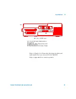


Breakout Box, LEDs, and Connectors
B
Advisor Mainframe Features System Guide
65
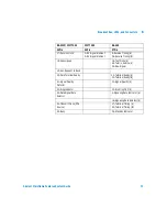
Lead Status LEDs
On the right side, rearward of the keyboard, are ten pairs of
LEDs that show a real-time indication of lead status for all of
the interfaces. These LEDs also indicate data, clock and control
information for the V-Series interfaces. The following list
provides information on the meaning of the lighted LEDs:
When the selected interface is RS-232/V.24, the left column
LEDs light when the signal level is more negative than -3.6 volts
and the right column LEDs light when the signal level is more
positive than +3.6 volts. This is a safety margin of 20% above
EIA-232D minimum signal requirements of -3.0 and -3.6 volts. If
the circuit under test is lighting the proper Advisor LEDs, then
there is enough signal present to allow any EIA-232D/RS-232
conforming device to receive the data and control signals. If the
circuit under test cannot light these LEDs, the signal levels are
too low for reliable reception.
For the Interface Modules, the left column shows the state of
the Equipment (or user) signal and the right column shows the
state of the Line (or central office) signal. Alarm and Error
indications cause their respective red LEDs to light. The green
Signal LEDs light if a signal is present. If there is no signal
present, the topmost red LED lights to indicate a loss of signal.
These LEDs can provide a visual indication as to whether a
V-Series device is physically DTE or DCE. First connect the
Advisor to the device under test and configure it for the Monitor
mode. If either the DTE/SD Mark or Space LED lights, the
device under test is DTE. If the DCE/RD Mark or Space LED
lights, the device under test is DCE. If the Advisor is to Simulate
a device under test, it must complement the device’s physical
characteristic. If the device is DTE, the Advisor must be DCE
and vice versa.
Left column
Red
Mark State for Data, Off State for Control Signals
Right column
Green
Space State for Data, On State for Control Signals
Both LEDs
lighted
Active signal toggling
Neither LED
lighted
No signal present
Содержание J2300D
Страница 2: ...Agilent Technologies Advisor Mainframe Features System Guide...
Страница 9: ...8 Advisor Mainframe Features System Guide...
Страница 14: ...13 Agilent Technologies 1 Mainframe Overview Introduction 14 Product Matrix 15...
Страница 19: ...18 Advisor Mainframe Features System Guide 1 Mainframe Overview...
Страница 31: ...30 Advisor Mainframe Features System Guide 3 Installing Removing Interface Modules...
Страница 39: ...38 Advisor Mainframe Features System Guide 4 Attaching Removing Undercradles...
Страница 115: ...114 Advisor Mainframe Features System Guide C Regulatory Information...
Страница 119: ...118 Advisor Mainframe Features System Guide Index...


