


Getting Started
2
Advisor Mainframe Features System Guide
21
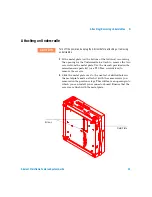
Starting the Advisor the First Time
Windows and Advisor software are already installed on the
hard drive at the factory. The software is included with your
shipment for recovery/re-installation only.
When you first power up the Advisor, you will need to enter
some initial Microsoft Windows setup information.
1
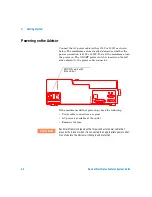
Plug in the Advisor and turn it on (the On/Off switch is
located next to the power cord on the left side of the unit).
2
Follow the instructions on the screen to enter a first and last
name, and to accept the Microsoft Windows license
agreement.
3
Enter the Microsoft Windows authenticity product ID#
affixed to the mainframe.
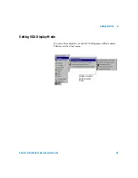
4
When the Date/Time Properties dialog is displayed, set the
date and time, select the time zone, and press Enter.
The time and date features are used for many of the
applications and reports generated by the Advisor. It is
important to set your local time and date when you receive
your Advisor. Setting the time and date also updates system
configuration files. The time and date are maintained even
when the Advisor is off.
5
After the Windows setup is complete, shut down and power
off the unit to update setup files and to prepare the Advisor
for running measurements.
Содержание J2300D
Страница 2: ...Agilent Technologies Advisor Mainframe Features System Guide...
Страница 9: ...8 Advisor Mainframe Features System Guide...
Страница 14: ...13 Agilent Technologies 1 Mainframe Overview Introduction 14 Product Matrix 15...
Страница 19: ...18 Advisor Mainframe Features System Guide 1 Mainframe Overview...
Страница 31: ...30 Advisor Mainframe Features System Guide 3 Installing Removing Interface Modules...
Страница 39: ...38 Advisor Mainframe Features System Guide 4 Attaching Removing Undercradles...
Страница 115: ...114 Advisor Mainframe Features System Guide C Regulatory Information...
Страница 119: ...118 Advisor Mainframe Features System Guide Index...


