background image

80

5977 Series MSD Operation Manual

3

Operating in Electron Ionization (EI) Mode

To Close the Analyzer Chamber

Materials needed

Gloves, clean, lint-free

Large (8650-0030)

Small (8650-0029)

Procedure

1

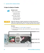
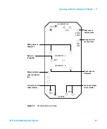
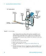
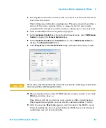
Ensure all the internal analyzer electrical leads are correctly attached. 
Wiring is the same for both the standard EI and CI ion sources. The 
extractor EI ion source has an extra wire leading to the extractor lens.

The wiring is described in 

Table

 14

 and illustrated in 

Figure

 13

 on page

 81 

and 

Figure

 14

 on page


82. The term “Board” in the table refers to the 

feedthrough board located next to the ion source.

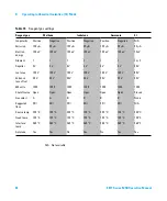
Table 14


Source board wiring

Wire description

Attached to

Connects to

Green beaded (2)

Quad heater

Board, top left (HTR)

White with braided cover (2)

Quad sensor

Board, top (RTD)

White (2)

Board, center (FILAMENT-1)

Filament 1 (top)

Red (1)

Board, center left (REP)

Repeller

Black (2)

Board, center (FILAMENT-2)

Filament 2 (bottom)

Orange (1)

Board, top right (ION FOC)

Ion focus lens

Blue (1)

Board, top right (ENT LENS)

Entrance lens

White beaded (2)

Ion source heater

Board, bottom left (HTR)

White (2)

Ion source sensor

Board, bottom (RTD)

Brown (1)

Extractor lens 
(Extractor EI ion source only)

Board, middle left


Содержание G7035A

Страница 1: ...Agilent Technologies Agilent 5977 Series MSD Operation Manual ...

Страница 2: ... of merchantability and fitness for a par ticular purpose Agilent shall not be liable for errors or for incidental or consequential damages in connec tion with the furnishing use or per formance of this document or of any information contained herein Should Agilent and the user have a separate written agreement with warranty terms covering the material in this document that conflict with these ter...

Страница 3: ...for use with the MSD install it in the GC oven and connect it to the MSD using the GC MSD interface 3 Operating in Electron Ionization EI Mode Chapter 3 describes basic tasks such as setting temperatures monitoring pressures tuning venting and pumpdown Much of the information in this chapter also applies to CI operation 4 Operating in Chemical Ionization CI Mode Chapter 4 describes additional task...

Страница 4: ...our instrument provides an extensive collection of online help videos and books for the Agilent 7890 Series GC 7820 GC 5977 Series MSD and the 7693A Included are localized versions of the information you need most such as Getting Familiar documentation Safety and Regulatory guides Installation information Operating guides Maintenance information Troubleshooting details ...

Страница 5: ...aning Recycling the Product 27 Liquid Spillage 27 Moving or Storing the MSD 27 To Replace the Primary Fuses 28 2 Installing GC Columns Columns 32 To Install a Capillary Column in a Split Splitless Inlet 34 To Condition a Capillary Column 37 To Install a Capillary Column in the GC MS Interface 38 To Prepare the Column Ends for a CFT Fitting 41 3 Operating in Electron Ionization EI Mode Operating th...

Страница 6: ... for MSD Temperature and Vacuum Status 59 To Set Analyzer Temperatures from the Instrument Control View 61 To Set the GC MSD Interface Temperature from MassHunter 63 To Monitor High Vacuum Pressure 64 To Calibrate Column Flow Linear Velocity 66 To Tune the MSD in EI Mode 69 To Verify System Performance 71 To Perform High Mass Testing 5977 Series MSDs 72 To Open the MSD Covers 75 To Vent the MSD 76...

Страница 7: ...ware for CI Operation 99 To Operate the Reagent Gas Flow Control Module 101 To Set Up Methane Reagent Gas Flow 104 To Use Other Reagent Gases 106 To Switch from the CI Ion Source to the Standard or Inert EI Ion Source 109 To Switch from the CI Ion Source to the Extractor EI Ion Source 110 To Perform a PCI Autotune Methane Only 111 To Perform an NCI Autotune Methane Reagent Gas 113 To Verify PCI Pe...

Страница 8: ... Extractor EI Ion Source 145 To Replace a Filament in an EI Ion Source 148 To Install the EI Ion Source 150 To Replace the Electron Multiplier Horn 151 6 CI Maintenance General Information 154 To set up your MSD for CI operation 154 To Install the CI Extractor Interface Tip Seal 155 To Remove the CI Ion Source 157 To Disassemble the CI Ion Source 159 To Clean the CI Ion Source 162 To Assemble the ...

Страница 9: ...iption 15 Important Safety Warnings 17 Hydrogen Safety 19 Safety and Regulatory Certifications 24 Cleaning Recycling the Product 27 Liquid Spillage 27 Moving or Storing the MSD 27 To Replace the Primary Fuses 28 This chapter describes general information about the 5977 Series MSDs including a hardware description general safety warnings and hydrogen safety information ...

Страница 10: ...n Ionization mode Type 5977E MSD Diff Pump for 7820 GC G7035A Diffusion pump Electron ionization EI Stainless Steel 5977E MSD Turbo Pump for 7820 GC G7036A Performance Turbo pump Electron ionization EI Stainless Steel 5977A VL inert MSD EI Diffusion Pump for 7890 Series GC G7037A Diffusion pump MSD Electron ionization EI Inert 5977A inert MSD EI Turbo for 7890 Series GC G7038A Performance turbo pu...

Страница 11: ... CI Chemical ionization DC Direct current DFTPP Decafluorotriphenylphosphine calibrant DIP Direct insertion probe DP Diffusion pump EI Electron ionization EM Electron multiplier detector EMV Electron multiplier voltage EPC Electronic pneumatic control eV Electron volt GC Gas chromatograph HED High energy dynode refers to detector and its power supply id Inside diameter LAN Local Area Network LCP L...

Страница 12: ... 5 8 dimethyl 3 6 9 trioxydodecane calibrant PFHT 2 4 6 tris perfluoroheptyl 1 3 5 triazine calibrant PFTBA Perfluorotributylamine calibrant Quad Quadrupole mass filter RF Radio frequency RFPA Radio frequency power amplifier Torr Unit of pressure 1 mm Hg Turbo Turbomolecular pump Table 2 Abbreviations continued Abbreviation Definition ...

Страница 13: ...ntly MSD heated hyperbolic quadrupole mass filter High energy dynode HED electron multiplier detector Independently GC heated GC MSD interface Physical description The 5977 Series MSD housing is approximately 41 cm high 30 cm wide and 54 cm deep The weight is 39 kg for the diffusion pump models 44 kg for the standard EI performance turbo pump mainframe and 46 kg for the EI CI performance turbo pum...

Страница 14: ...ptimal He column flow mL min 1 1 to 2 1 1 to 2 1 to 2 1 to 2 Maximum recommended gas flow mL min 1 5 4 1 5 4 4 4 Maximum gas flow mL min 2 6 5 2 6 5 6 5 6 5 Max column id 0 25 mm 30 m 0 53 mm 30 m 0 25 mm 30 m 0 53 mm 30 m 0 53 mm 30 m 0 53 mm 30 m CI capability No No No No No Yes Inert material No No Yes Yes No No GC compatibility 7820 7820 7890 Series 7890 Series 7890 Series 7890 Series Separate...

Страница 15: ...ion 1 5977 Series MSD Operation Manual 15 MSD Hardware Description Figure 1 5977 Series GC MSD system shown with Agilent 7890B GC ALS 7890B GC Local control panel 5977 Series MSD MSD power switch GC power switch ...

Страница 16: ... hydrocarbons and sulfur compounds A high vacuum gauge controller G3397B is integrated in the system Its use is required for CI MSD and is recommended for EI also The MSD CI system has been optimized to achieve the relatively high CI ion source pressure required for CI while still maintaining high vacuum in the quadrupole and detector Special seals along the flow path of the reagent gas and very s...

Страница 17: ...y fuses has failed the MSD will already be off but for safety you should switch off the MSD and unplug the power cord It is not necessary to allow air into the analyzer chamber Electrostatic discharge is a threat to MSD electronics The printed circuit boards in the MSD can be damaged by electrostatic discharge Do not touch any of the boards unless it is absolutely necessary If you must handle them...

Страница 18: ...intaining before you begin working on it The oil pan under the standard foreline pump can be a fire hazard Oily rags paper towels and similar absorbents in the oil pan could ignite and damage the pump and other parts of the MSD WARNING Be careful when working behind the instrument During cool down cycles the GC emits hot exhaust which can cause burns WARNING The insulation around the GC inlets det...

Страница 19: ...stic cover for the MSD transfer line located on the GC left side panel In the unlikely event of an explosion this cover may dislodge WARNING Using hydrogen as a GC carrier gas is potentially dangerous WARNING When using hydrogen H2 as the carrier gas or fuel gas be aware that hydrogen can flow into the GC oven and create an explosion hazard Therefore be sure that the supply is turned off until all...

Страница 20: ...mentation and the label on the top edge of the GC oven door Accumulation of hydrogen in the MSD and subsequent combustion Hydrogen accumulation in an MSD All users should be aware of the mechanisms by which hydrogen can accumulate Table 4 on page 21 and know what precautions to take if they know or suspect that hydrogen has accumulated Note that these mechanisms apply to all mass spectrometers inc...

Страница 21: ...pped with manual diffusion pump shutoff valves In these instruments the operator can close the shutoff valves Closing the shutoff valves does not shut off the flow of carrier gas As a result hydrogen may slowly accumulate in the mass spectrometer GC off A GC can be shut down deliberately It can also be shut down accidentally by an internal or external failure Different GCs react in different ways ...

Страница 22: ...atory as many ignition sources as possible open flames devices that can spark sources of static electricity etc Do not allow hydrogen from a high pressure cylinder to vent directly to atmosphere danger of self ignition Use a hydrogen generator instead of bottled hydrogen WARNING Once hydrogen has accumulated in a mass spectrometer extreme caution must be used when removing it Incorrect startup of ...

Страница 23: ...rs while the GC MSD system is unattended even if the system has restarted by itself 1 Immediately turn off the hydrogen at its source 2 Turn off the GC 3 Turn off the MSD and allow it to cool for 1 hour 4 Eliminate all potential sources of ignition in the room 5 Open the vacuum manifold of the MSD to atmosphere 6 Wait at least 10 minutes to allow any hydrogen to dissipate 7 Start up the GC and MSD...

Страница 24: ...SD is designed and manufactured under a quality system registered to ISO 9001 Information The Agilent Technologies 5977 Series MSD meets the following IEC International Electro technical Commission classifications Equipment Class I Laboratory Equipment Installation Category II Pollution Degree 2 This unit has been designed and tested in accordance with recognized safety standards and is designed f...

Страница 25: ...tended use of the instrument Agilent Technologies assumes no liability for the customer s failure to comply with these requirements See accompanying instructions for more information Indicates a hot surface Indicates hazardous voltages Indicates earth ground terminal Indicates potential explosion hazard Indicates radioactivity hazard Indicates electrostatic discharge hazard Indicates that you must...

Страница 26: ...e or more of the following measures 1 Relocate the radio or antenna 2 Move the device away from the radio or television 3 Plug the device into a different electrical outlet so that the device and the radio or television are on separate electrical circuits 4 Ensure that all peripheral devices are also certified 5 Ensure that appropriate cables are used to connect the device to peripheral equipment ...

Страница 27: ...fice Liquid Spillage Do not spill liquids on the MSD Moving or Storing the MSD The best way to keep your MSD functioning properly is to keep it pumped down and hot with carrier gas flow If you plan to move or store your MSD a few additional precautions are required The MSD must remain upright at all times this requires special caution when moving The MSD should not be left vented to atmosphere for...

Страница 28: ...eady be off but for safety you should switch off the MSD and unplug the power cord It is not necessary to allow air into the analyzer chamber 2 Turn one of the fuse holders Figure 2 on page 29 counterclockwise until it pops out The fuse holders are spring loaded 3 Remove the old fuse from the fuse holder 4 Install a new fuse in the fuse holder 5 Reinstall the fuse holder WARNING Never replace the ...

Страница 29: ...ries MSD Operation Manual 29 6 Repeat steps 3 through 5 for the other fuse Always replace both fuses 7 Reconnect the MSD power cord to the electrical outlet 8 Pump down the MSD Figure 2 Primary fuses Primary fuses in holders ...

Страница 30: ...30 5977 Series MSD Operation Manual 1 Introduction ...

Страница 31: ...ary Column in the GC MS Interface 38 To Prepare the Column Ends for a CFT Fitting 41 Before you can operate your GC MSD system you must select install and condition a GC column This chapter shows you how to install and condition a column For correct column and flow selection you must know what type of vacuum system your MSD has The serial number tag on the lower front of the left side panel shows ...

Страница 32: ... Flow Calculation software and Table 5 to determine whether a given column will give acceptable flow with realistic head pressure Table 5 Gas flows Model Feature G7035A G7036A G7037A G7038A G7039A G7040A High vacuum pump Diffusion Performance turbo Diffusion Performance turbo Performance turbo Performance turbo Optimal He column flow mL min 1 1 to 2 1 1 to 2 1 to 2 1 to 2 Maximum recommended gas f...

Страница 33: ...they are installed can reduce chemical bleed from the ferrules Tips and hints The column installation procedures for the 5977 Series MSDs may be different from that for previous MSDs Using the procedure from another instrument may not work and may damage the column or the MSD You can remove old ferrules from column nuts with an ordinary push pin Always use carrier gas that is at least 99 9995 pure...

Страница 34: ...16 0 40 mm id for 0 25 mm id columns 5181 3323 0 5 mm id for 0 32 mm id columns 5062 3514 0 8 mm id for 0 53 mm id columns 5062 3512 Inlet column nut 5181 8830 for Agilent 7890 Series and 7820 Magnifying loupe Septum may be old used inlet septum To install columns in other types of inlets refer to your Gas Chromatograph User Information WARNING The GC operates at high temperatures In order to avoi...

Страница 35: ...nd 4 While holding the column against the column cutter with your thumb break the column against the edge of the column cutter 5 Inspect the end for jagged edges or burrs If the break is not clean and even repeat steps 3 and 4 6 Wipe the outside of the free end of the column with a lint free cloth moistened with methanol CAUTION Always wear clean gloves while handling any parts that go inside the ...

Страница 36: ...he column nut 12 Tighten the column nut an additional 1 4 to 1 2 turn The column should not slide with a gentle tug 13 Start carrier gas flow 14 Verify flow by submerging the free end of the column in isopropanol Look for bubbles See also For more information about installing a capillary column refer to Optimizing Splitless Injections on Your GC for High Performance MS Analysis Agilent Technologie...

Страница 37: ...e the temperature at a rate of 10 to 15 C min 5 Hold at the maximum temperature for 30 minutes 6 Set the GC oven temperature to 30 C and wait for the GC to become ready 7 Attach the column to the GC interface See To Install a Capillary Column in the GC MS Interface on page 38 WARNING Do not condition your capillary column with hydrogen Hydrogen accumulation in the GC oven can result in an explosio...

Страница 38: ...ge 41 Agilent 7890 Series GC Materials needed Column cutter ceramic 5181 8836 or diamond 5183 4620 Ferrules 0 3 mm id for 0 10 mm id columns 5062 3507 0 4 mm id for 0 20 and 0 25 mm id columns 5062 3508 0 5 mm id for 0 32 mm id columns 5062 3506 0 8 mm id for 0 53 mm id columns 5062 3512 Flashlight Magnifying loupe Gloves clean Large 8650 0030 Small 8650 0029 Interface column nut 05988 20066 Safet...

Страница 39: ...and 5 7 Wipe the end with alcohol 8 Insert the column into the column measuring tool 9 Slide the column so that the end projects 1 2 mm past the end of the tool 10 Finger tighten the fitting 11 Tighten 1 4 to 1 2 turn to fix the ferrule to the column 12 Slide the column into the GC MS interface WARNING The analyzer GC MS interface and other components in the analyzer chamber operate at very high t...

Страница 40: ... the nut Ensure the position of the column does not change as you tighten the nut 14 Check the GC oven to be sure that the column does not touch the oven walls 15 Tighten the nut 1 4 to 1 2 turn 16 Check the nut s tightness after one or two heat cycles retighten as appropriate ...

Страница 41: ...d 5 16 inch 8710 0510 Procedure 1 Obtain the appropriate metal ferrule 2 Pass the tubing end through the internal nut and SilTite ferrule leaving approximately 1 cm of fused silica tubing protruding beyond the ferrule Thread the ferrule pre swaging tool onto the internal nut with the tube protruding see Figure 5 Figure 5 Assemble the internal nut ferrule and swaging nut CAUTION The SilTite ferrule...

Страница 42: ...f the ferrule is gripping the tube see Figure 6 When the ferrule just starts to grip notice position of the nut and then tighten by turning 45 to 60 degrees of rotation but no more than 60 degrees one flat If you can pull the column free it is not tight enough 4 Remove the swaging tool Figure 7 Figure 6 Tightening the internal nut Figure 7 Removed ferrule pre swaging tool ...

Страница 43: ...ge 43 It is important that the ceramic column cutter have one side dedicated to only make contact with the column and the other side dedicated to riding on the edge of the metallic SilTite ferrule This preserves the ceramic edge sharpness which is necessary to making good column cuts NOTE It is important that the tube end does not extend beyond 0 5 mm from the end of the ferrule Figure 8 Ceramic c...

Страница 44: ...t have cracks which extend under the ferrule Figure 9 shows a completed tube end 7 Connect column to the Quick Swap or PUU with internal nuts and preswaged SilTite ferrules Figure 10 Finger tighten the nuts Further tighten with a wrench only 15 to 20 degrees Figure 9 Tube end with internal nut and swaged SilTite ferrule Figure 10 Completed Ultimate union with columns ...

Страница 45: ...um Status 59 To Set Analyzer Temperatures from the Instrument Control View 61 To Set the GC MSD Interface Temperature from MassHunter 63 To Monitor High Vacuum Pressure 64 To Calibrate Column Flow Linear Velocity 66 To Tune the MSD in EI Mode 69 To Verify System Performance 71 To Perform High Mass Testing 5977 Series MSDs 72 To Open the MSD Covers 75 To Vent the MSD 76 To Open the Analyzer Chamber...

Страница 46: ...ment itself Because the LCP communicates with the Data Acquisition software through the LAN you can access Data Acquisition software functions such as tuning and starting a run right from the MSD Only certain features are available from the LCP The Data Acquisition software is the full featured controller for most instrument control operations Modes of operation The LCP has two modes of operation ...

Страница 47: ...atically returns to Status mode Pressing Menu then No Cancel will always display the Status mode Pressing No Cancel twice will always return to the Status mode Press Menu until the desired menu appears Press Item until the desired menu item appears Use Up to increase the displayed value or to scroll up such as in a message list Use Down to decrease the displayed value or to scroll down such as in ...

Страница 48: ...une Instrument Available timestamp The Agilent MassHunter Data Acquisition software is not running Loading Method method name Method parameters are being sent to the MSD Loading MSD Firmware The MSD s firmware is being initialized The following messages alternately appear on the LCP if the MSD does NOT complete its bootup sequence properly Server not Found Check LAN Connection Seeking Server Bootp...

Страница 49: ...from the MassHunter Data Acquisition Press Sideplate A reminder during startup to press the MSD side plate to ensure an adequate vacuum seal Run method Acquiring datafile A run is in progress data is being acquired to the designated data file To view system status during startup 1 The following messages are displayed on the LCP display during startup Press Sideplate Loading OS Press Sideplate Load...

Страница 50: ...ce Run Current Tune Displays the current tune file and starts an autotune EI mode only CI tune must be started from the MassHunter Data Acquisition of Messages Displays the number of messages and the text of the most recent message Use the arrow keys to scroll through previous messages up to 20 Release ChemStation Disassociates the MassHunter Data Acquisition from the MSD Connection Status Display...

Страница 51: ...talled Turbo Pump Speed Displays the turbo pump speed MSD Fault Status Reports a summary fault status code number in dec decimal and hex hexadecimal format covering all possible fault combinations Ion Source Temp oC Displays and sets the ion source temperature Quadrupole Temp oC Displays and sets the quadrupole temperature CI Reagent Displays CI reagent gas and flow rate if installed NOTE MS param...

Страница 52: ...settings Table 10 Version menu Action Description Control firmware Displays the MSD firmware version Operating system Displays the MassHunter Data Acquisition operating system version Front panel Displays the version of the LCP Log amplifier Displays version information Sideboard Displays the sideboard type Mainboard Displays the mainboard type Serial number Is assigned to the MSD by MassHunter Da...

Страница 53: ...controlled by Thermal Aux 2 heated zone of the GC The interface temperature can be set from MassHunter Data Acquisition or from the gas chromatograph A sensor thermocouple in the interface monitors the temperature The GC MSD interface should be operated in the 250 to 350 C range Subject to that restriction the interface temperature should be slightly higher than the maximum GC oven temperature but...

Страница 54: ...3 Operating in Electron Ionization EI Mode Figure 11 The EI GC MSD interface Ionization chamber Analyzer chamber Heater Sensor assembly MSD GC oven Heater sleeve Insulation Column Column end protrudes 1 to 2 mm into the ionization chamber ...

Страница 55: ...nded traps If hydrogen is used as carrier gas carrier gas flow must be off and the front sideplate thumbscrew must be loosely fastened The foreline pump exhaust is properly vented WARNING The exhaust from the foreline pump contains solvents and the chemicals you are analyzing If using the standard foreline pump it also contains traces of pump oil If you are using toxic solvents or analyzing toxic ...

Страница 56: ...ontroller The LCP can also display these data Controlling Temperatures MSD temperatures are controlled through the data system The MSD has independent heaters and temperature sensors for the ion source and quadrupole mass filter You can adjust the setpoints and view these temperatures from the data system or from the local control panel Normally the GC MSD interface heater is powered and controlle...

Страница 57: ...efore the diffusion pump has fully cooled A turbo pump will be damaged if it is vented while spinning at more than 50 of its normal operating speed WARNING Make sure the GC MSD interface and the analyzer zones are cool below 100 C before you vent the MSD A temperature of 100 C is hot enough to burn skin always wear cloth gloves when handling analyzer parts WARNING If you are using hydrogen as a ca...

Страница 58: ...emperature Setpoint or Limit enter the new parameters and click Apply Unless you have just begun the pumpdown process the foreline pressure should be less than 300 mTorr or the turbo pump should be running at least 80 speed MSD heaters remain off as long as the diffusion pump is cold or the turbo pump is operating at less than 80 Normally the foreline pressure will be below 100 mTorr or the turbo ...

Страница 59: ...a user determined limit from its setpoint Procedure 1 In Instrument Control view select Edit Monitors from the Instrument menu to display the Select Monitors dialog 2 In the Available Monitors column select a monitor and click the Add button to move the selection to the Selected Monitors column Repeat for additional monitors 3 Click OK The new monitors will be stacked on top of each other in the l...

Страница 60: ...ew to open that monitor s dialog for setting alarms a Select the Set Alarm check box b Set the Warning Level Alarm Level and Below Minimum to appropriate values c Enter descriptive text in the Monitor Label field if the default label is not appropriate d Click OK to finish the monitor s alarm configuration 6 To make the new settings part of the method save the Method ...

Страница 61: ...nt Control view select MS Temperatures from the Instrument menu 2 Enter the MS Source and MS Quad mass filter temperatures in the Setpoint and Limit fields See Table 12 The GC MSD interface ion source and quadrupole heated zones interact The analyzer heaters may not be able to accurately control temperatures if the setpoint for one zone is much different from that of an adjacent zone Table 12 Reco...

Страница 62: ...currently loaded tune file and download these parameters to the MSD click Apply 4 Click Close to exit the dialog If changes were made to any parameters the Save MS Tune File dialog displays Click OK to save your changes to the same file or type a new file name and click OK Click Cancel to discard the edit made to any parameter ...

Страница 63: ...he Value C column The typical setpoint is 280 C The limits are 0 C and 350 C A setpoint below ambient temperature turns off the interface heater 4 Click Apply to download setpoints or click OK to download setpoints and close the window 5 To make the new settings part of the method select Save from the Method menu CAUTION Ensure that the carrier gas is turned on and the column has been purged of ai...

Страница 64: ... the Tune and Vacuum Control view select Turn Vacuum Gauge on off from the Vacuum menu 3 Select Manual Tune from the Parameters menu to display the Manual Tune dialog 4 Select the Values tab to view the HiVac reading WARNING If you are using hydrogen as a carrier gas do not turn on the Micro Ion vacuum gauge if there is any possibility that hydrogen has accumulated in the analyzer chamber Read Hyd...

Страница 65: ...r Data Acquisition software for information on troubleshooting air leaks and other vacuum problems In the Instrument Control view you can set up an MS Monitor for displaying this vacuum reading The vacuum can also be read on the LCP or from the Manual Tune screen Table 13 Ion vacuum gauge reading Column flow rate mL min Optional Gauge reading Torr Performance turbo pump Gauge reading Torr Diffusio...

Страница 66: ...set up a real time plot to monitor m z 28 2 Press Prep Run on the GC keypad 3 Inject 1 µL of air into the GC inlet and press Start Run 4 Wait until a peak elutes at m z 28 Note the retention time 5 In the Instrument Control view select GC Parameters from the Instrument menu 6 Select the Configuration tab and then select the Columns tab 7 Select your installed column from the table 8 Click the Cali...

Страница 67: ... used in the method to determine the holdup time Change any parameters that are different than those used in your method 11 Enter the recorded retention time in the Holdup Time field Move the cursor to another parameter s field and the calibrated column length appears 12 Click OK to save the changes and exit the dialog 13 Click OK on the Calibrate Columns dialog to save the calibration With capill...

Страница 68: ...e linear velocity Average linear velocity cm s where L Length of the column in meters t Retention time in seconds Calculation for volumetric flow rate Volumetric flow rate mL min where D Internal column diameter in millimeters L Column length in meters t Retention time in minutes 100 L t 0 785 D 2 L t ...

Страница 69: ... different tune file select MS Tune File from the Instrument menu to display the Select Tune File dialog The Settings area displays the important parameters for a selected tune file The tune file must match the type of ion source in the analyzer If you are using an EI ion source select a tune file created for an EI ion source 4 Click the MS Tune icon to display the Select Tune Type dialog 5 Select...

Страница 70: ...ut menu To view history of tune results in the Instrument Control view select Checkout View Previous Tunes To manually tune your MSD or to perform special autotunes from the View menu select Tune and Vacuum Control view See the manuals and online help provided with your MassHunter Data Acquisition software for additional information about tuning ...

Страница 71: ...Checkout menu The software will evaluate the last autotune and print a System Verification Tune report Verify the sensitivity performance 1 Set up to inject 1 µL of OFN either with the ALS or manually 2 In the Instrument Control view select Sensitivity Check from the Checkout menu The system displays an Alert dialog reminder about resolving the OFN_SN method and placing the OFN sample in vial 1 wh...

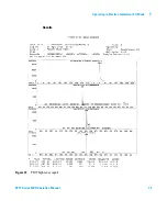
Страница 72: ... See To Tune the MSD in EI Mode on page 69 2 Resolve the PFHT M method under x 5977 PFHT M where x is the instrument number being used 3 Update and save the method 4 Load the PFHT calibration sample into a vial and place in position 2 5 In Instrument Control view select High Mass Check from the Checkout menu 6 Follow the instructions on screen 7 The Run is completed and results are printed within ...

Страница 73: ...Operating in Electron Ionization EI Mode 3 5977 Series MSD Operation Manual 73 Results Figure 12 PFHT high mass report ...

Страница 74: ...sub tab 4 Select the Enable This Lens checkbox 5 Enter the recommend dynamic offset Voltage V and click OK 6 Click Save to save this dynamic Amu Offset for the high mass You can overwrite the existing ATUNE U to include high mass adjustment or save this file to a new name for example ATUNEHIGH U Anytime an ATUNE U is performed it will overwrite this dynamic Amu Offset that was entered This is why ...

Страница 75: ... the window slightly forward and lift off the MSD To open the analyzer cover Pull the handle on the side of the MSD to the left and down to release the magnetic latch and open the cover The cover is held in place by its hinges CAUTION Do not use excessive force or the plastic tabs that hold the cover to the mainframe will break off Analyzer window cover Handle Analyzer cover WARNING Do not remove ...

Страница 76: ...rol view select Edit Tune Parameters from the Instrument menu to display the Manual Tune dialog 3 Select the Values tab and set the MS Source and MS Quad temperatures to ambient room temperature and click Apply to download these settings to the MSD WARNING If you are using hydrogen as a carrier gas the carrier gas flow must be off before turning off the MSD power If the foreline pump is off hydrog...

Страница 77: ...cover see To Open the MSD Covers on page 75 6 Click Vent to begin the automated shutdown of the MSD Follow the instructions presented 7 When prompted turn the vent valve knob counterclockwise only 3 4 turns or until you hear the hissing sound of air flowing into the analyzer chamber Do not turn the knob too far or the O ring may fall out of its groove Be sure to close the vent valve before pumping...

Страница 78: ...970 Procedure 1 Vent the MSD see To Vent the MSD on page 76 2 Disconnect the side board control cable and the source power cable from the side board CAUTION Electrostatic discharges to analyzer components are conducted to the side board where they can damage sensitive components Wear a grounded antistatic wrist strap and take other antistatic precautions page 123 before opening the analyzer chambe...

Страница 79: ...es are used for carrier gas 4 Gently swing the side plate out CAUTION In the next step if you feel resistance stop Do not try to force the side plate open Verify that MSD is vented Verify that both the front and rear side plate screws are completely loose WARNING The analyzer GC MSD interface and other components in the analyzer chamber operate at very high temperatures Do not touch any part until...

Страница 80: ... and Figure 14 on page 82 The term Board in the table refers to the feedthrough board located next to the ion source Table 14 Source board wiring Wire description Attached to Connects to Green beaded 2 Quad heater Board top left HTR White with braided cover 2 Quad sensor Board top RTD White 2 Board center FILAMENT 1 Filament 1 top Red 1 Board center left REP Repeller Black 2 Board center FILAMENT ...

Страница 81: ...ring HTR RTS SOURCE FILAMENT 2 FILAMENT 1 REP ION FOC ENTR LENS HTR RTS QUADRUPOLE White wires to filament 1 Red wire to repeller Black wires to filament 2 Ion source heater wires white Blue wire to entrance lens Orange wire to ion focus lens Ion source sensor wires white Brown extractor wire to extractor lens ...

Страница 82: ...Close the side plate 3 Reconnect the side board control cables 4 Make sure the vent valve is closed 5 Pump down the MSD See To Pump Down the MSD in EI Mode on page 84 6 If you are operating in CI mode or if hydrogen or other flammable or toxic substance is used for carrier gas gently hand tighten the front side plate thumbscrew Figure 14 Ion source wiring FB Feedthrough Board Ion source heater wir...

Страница 83: ...ont thumbscrew must be fastened for CI operation or if hydrogen or other hazardous gas is being used as the GC carrier gas In the unlikely event of an explosion it may prevent the side plate from opening CAUTION Do not overtighten the thumbscrew it can cause air leaks or prevent successful pumpdown Do not use a screwdriver to tighten the thumbscrew ...

Страница 84: ...e MSD power cord 4 Press the Power on button on the front of the MSD WARNING Make sure your MSD meets all the conditions listed in the introduction to this chapter page 53 before starting up and pumping down the MSD Failure to do so can result in personal injury WARNING If you are using hydrogen as a carrier gas do not start carrier gas flow until the MSD has been pumped down If the vacuum pumps a...

Страница 85: ...m Control dialog 8 In the Instrument Control view Instrument menu select MS Vacuum Control to display the Vacuum Control dialog 9 Click Pump Down in the Vacuum Control dialog and follow the system prompts 10 When prompted turn on the GC MSD interface heater and GC oven Click OK when you have done so The software will turn on the ion source and mass filter quad heaters The temperature setpoints are...

Страница 86: ... blank ferrule and interface nut 3 Tighten the vent valve 4 Move the MSD away from the GC see the 5977 Series MSD Troubleshooting and Maintenance Manual 5 Unplug the GC MSD interface heater cable from the GC 6 Open the analyzer cover See To Open the MSD Covers on page 75 7 Finger tighten the side plate thumbscrews CAUTION Do not overtighten the side plate thumbscrews Overtightening will strip the ...

Страница 87: ...he MSD off 11 Close the analyzer cover 12 Disconnect the LAN remote and power cables The MSD can now be stored or moved The foreline pump cannot be disconnected it must be moved with the MSD Make sure the MSD remains upright and is never tipped on its side or inverted CAUTION The MSD must remain upright at all times If you need to ship your MSD to another location contact your Agilent Technologies...

Страница 88: ...88 5977 Series MSD Operation Manual 3 Operating in Electron Ionization EI Mode ...

Страница 89: ...on Source 109 To Switch from the CI Ion Source to the Extractor EI Ion Source 110 To Perform a PCI Autotune Methane Only 111 To Perform an NCI Autotune Methane Reagent Gas 113 To Verify PCI Performance 115 To Verify NCI Performance 116 To Monitor CI Mode High Vacuum Pressure 117 This chapter provides information and instructions for operating the 5977 Series CI MSDs in Chemical Ionization CI mode ...

Страница 90: ...Always verify the MSD is performing well in EI mode before switching to CI See To Verify System Performance on page 71 Make sure the CI ion source and GC MSD interface tip seal are installed Make sure the reagent gas plumbing has no air leaks This is determined in PCI mode checking for m z 32 after the methane pretune Make sure the reagent gas inlet line is equipped with gas purifiers not applicab...

Страница 91: ... reagent gas enters the interface body and mixes with carrier gas and sample in the ion source The GC MSD interface is heated by an electric cartridge heater Normally the heater is powered and controlled by Thermal Aux 2 heated zone of the GC The interface temperature can be set from MassHunter Data Acquisition or from the gas chromatograph A sensor thermocouple in the interface monitors the tempe...

Страница 92: ...ing in Chemical Ionization CI Mode See Also To Install a Capillary Column in the GC MS Interface on page 38 Figure 15 The CI GC MSD interface Spring loaded seal Reagent gas in MSD GC oven Column end protrudes 1 to 2 mm into the ionization chamber ...

Страница 93: ... any reagent gas Always tune for methane PCI first regardless of which mode or reagent gas you wish to use for your analysis There are no tune performance criteria If CI autotune completes it passes EMVolts electron multiplier voltage at or above 2600 V however indicates a problem If your method requires EMVolts set at 400 you may not have adequate sensitivity in your data acquisition CAUTION Afte...

Страница 94: ...0 eV 70 eV Filament 1 1 1 1 1 1 1 or 2 Repeller 3 V 3 V 3 V 3 V 3 V 3 V 30 V Ion focus 130 V 130 V 130 V 130 V 130 V 130 V 90 V Entrance lens offset 20 V 20 V 20 V 20 V 20 V 20 V 25 V EM volts 1200 1400 1200 1400 1200 1400 1300 Shutoff valve Open Open Open Open Open Open Closed Gas select A A B B B B None Suggested flow 20 40 20 40 20 40 N A Source temp 250 C 150 C 250 C 150 C 250 C 150 C 230 C Qu...

Страница 95: ...atio in the methane flow adjust panel Tell if a gross air leak is present by monitoring the ions at m z 19 protonated water and 32 Confirm that the MS is generating real ions and not just background noise It is nearly impossible to perform any diagnostics on the system in NCI In NCI there are no reagent gas ions to monitor It is difficult to diagnose an air leak and difficult to tell whether a goo...

Страница 96: ...face tip seal p n G3870 20542 See To Install the CI Extractor Interface Tip Seal on page 155 6 Close the analyzer See To Close the Analyzer Chamber on page 80 7 Pump down the MSD See To Pump Down the MSD in CI Mode on page 98 CAUTION Always verify MSD performance in EI before switching to CI operation Always set up the CI MSD in PCI first even if you are going to run NCI CAUTION Electrostatic disc...

Страница 97: ...See Figure 13 on page 81 5 Install the CI ion source See To Install the CI Ion Source on page 167 6 Close the analyzer See To Close the Analyzer Chamber on page 80 7 Pump down the MSD See To Pump Down the MSD in CI Mode on page 98 CAUTION Always verify MSD performance in EI before switching to CI operation Always set up the CI MSD in PCI first even if you are going to run NCI CAUTION Electrostatic...

Страница 98: ...l Tune dialog click the Values tab to monitor that the pressure is decreasing Hi Vac gauge option installed 3 In the Manual Tune dialog click the CI Gas tab then in the Valve Settings area close Gas Valve A Gas Valve B and the ShutOff Valve 4 Verify that PCICH4 U is loaded top left in Manual Tune dialog and click the Values tab to accept the temperature setpoints Always start up and verify system ...

Страница 99: ... for default values for the Tune Control Limits box These limits are used by Autotune only They should not be confused with the parameters set in Edit MS Parameters or with those appearing on the tune report Notes for Table 17 N A Not available There are no PFDTD ions formed in PCI with any reagent gas but methane hence CI autotune is not available with these configurations CAUTION Always verify G...

Страница 100: ...red signal abundance Higher signal abundance also gives higher noise abundance This is adjusted for data acquisition by setting the EMV in the method Peakwidth target Higher peakwidth values give better sensitivity lower values give better resolution Maximum emission current Optimum emission current maximum for NCI is very compound specific and must be selected empirically Optimum emission current...

Страница 101: ...urrent tune file The system evacuates the gas lines for 6 minutes then turns on the selected gas A or B This is to reduce cross mixing of the gases in the lines CAUTION After the system has been switched from EI to CI mode or vented for any other reason the MS must be baked out for at least 2 hours before tuning CAUTION Continuing with CI autotune if the MS has an air leak or large amounts of wate...

Страница 102: ...lines Typical evacuation time is 6 minutes and then the shutoff valve is closed The flow control module The CI reagent gas flow control module regulates the flow of reagent gas into the CI GC MSD interface The flow module consists of a mass flow controller MFC gas select valves CI calibration valve shutoff valve control electronics and plumbing See Figure 16 and Table 18 on page 103 The back panel...

Страница 103: ...B flow Purge with Gas A Purge with Gas B Pump out flow module Standby vented or EI mode Gas A Open Closed Open Closed Closed Closed Gas B Closed Open Closed Open Closed Closed MFC On setpoint On setpoint On 100 On 100 On 100 Off 0 Shutoff valve Open Open Open Open Open Closed Gas A methane supply Gas B other supply Gas A select valve Gas B select valve Mass flow controller Calibration valve Restri...

Страница 104: ...ource See To Install the CI Ion Source on page 167 4 Pump out the system See To Pump Down the MSD in CI Mode on page 98 5 Wait until the pressure is near the previously recorded pressure for the EI autotune See To Monitor CI Mode High Vacuum Pressure on page 117 6 Select Bake out MSD from the Manual Tune view Execute menu to display the Specify Bake Out parameters dialog Set for a minimum time of ...

Страница 105: ...n air leak will rapidly contaminate the ion source The peak at m z 19 protonated water is less than 50 of the peak at m z 17 9 When prompted click OK to perform the methane Flow Adjust Methane pretune after more than a day of baking out Note the low abundance of m z 19 and absence of any visible peak at m z 32 Your MSD will probably show more water at first but the abundance of m z 19 should still...

Страница 106: ...s the life span of the filament CAUTION Not all setup operations can be performed in all modes with all reagent gases See Table 19 for details Table 19 Reagent gases Reagent gas mode Reagent ion masses PFDTD Calibrant ions Flow adj ions Ratio EI PCI NCI MSD Performance turbo pump Recommended flow 20 PCI 40 NCI Methane PCI 17 29 41 41 267 599 28 27 1 5 5 0 Methane NCI 17 35 235 185 351 449 N A Isob...

Страница 107: ...monia chemical ionization spectra often result from the addition of NH4 and then in some cases from the subsequent loss of water Ammonia reagent ion spectra have principal ions at m z 18 35 and 52 corresponding to NH4 NH4 NH3 and NH4 NH3 2 To adjust your MSD for isobutane or ammonia chemical ionization use the following procedure Procedure 1 Perform a standard Positive CI autotune with methane and...

Страница 108: ...tly a mixture of 5 ammonia and 95 helium or 5 ammonia and 95 methane is used as a CI reagent gas This is enough ammonia to achieve good chemical ionization while minimizing its negative effects Carbon dioxide CI Carbon dioxide is often used as a reagent gas for CI It has obvious advantages of availability and safety CAUTION Use of ammonia affects the maintenance requirements of the MSD See CI Main...

Страница 109: ...eal on page 155 4 Install the EI ion source See To Install the EI Ion Source on page 150 5 Place the CI ion source and interface tip seal in the ion source storage box 6 Pump down the MSD See To Pump Down the MSD in EI Mode on page 84 7 Load your EI tune file CAUTION Always wear clean gloves while touching the analyzer or any other parts that go inside the analyzer chamber CAUTION Electrostatic di...

Страница 110: ...tractor EI ion source 4 Install the EI extractor ion source See To Install the EI Ion Source on page 150 5 Locate the brown extractor wire from storage and connect it to the extractor lens and the source board 6 Place the CI ion source in the ion source storage box 7 Pump down the MSD See To Pump Down the MSD in EI Mode on page 84 8 Load your EI tune file CAUTION Always wear clean gloves while tou...

Страница 111: ... CI Autotune There are no tune performance criteria If autotune completes it passes See Figure 18 on page 112 If the tune sets the electron multiplier voltage EMVolts at or above 2600 V however you may not be able to acquire data successfully if your method sets EMVolts to 400 or higher The autotune report contains information about air and water in the system See PCI autotune report on page 112 T...

Страница 112: ...112 5977 Series MSD Operation Manual 4 Operating in Chemical Ionization CI Mode Figure 18 PCI autotune report ...

Страница 113: ...he Tune menu click CI Autotune There are no tune performance criteria If autotune completes it passes See Figure 19 on page 114 If the tune sets the electron multiplier voltage EMVolts at or above 2600 V however you may not be able to acquire data successfully if your method sets EMVolts to 400 or higher CAUTION Always verify MSD performance in EI before switching to CI operation See To Verify Sys...

Страница 114: ...114 5977 Series MSD Operation Manual 4 Operating in Chemical Ionization CI Mode Figure 19 NCI autotune ...

Страница 115: ... See To Switch from the CI Ion Source to the Extractor EI Ion Source on page 110 5 Run CI Autotune See CI Autotune on page 93 6 Run the PCI sensitivity method BENZ_PCI M using 1 µL of 100 pg µL benzophenone 7 Verify that the system conforms to the published sensitivity specification Please see the Agilent Web site at www agilent com chem for specifications CAUTION Always verify MSD performance in ...

Страница 116: ...trol view run CI Autotune See To Perform an NCI Autotune Methane Reagent Gas on page 113 Note that there are no criteria for a passing Autotune in CI If the Autotune completes it passes 5 Run the NCI sensitivity method OFN_NCI M using 2 µL of 100 fg µL OFN 6 Verify that the system conforms to the published sensitivity specification Please see the Agilent Web site at www agilent com chem for specif...

Страница 117: ...olumn flow Table 20 on page 118 lists typical pressures for various helium carrier gas flows These pressures are approximate and vary from instrument to instrument Typical pressure readings Use the G3397B Micro Ion vacuum gauge Note that the mass flow controller is calibrated for methane and the vacuum gauge is calibrated for nitrogen so these measurements are not accurate but are intended as a gu...

Страница 118: ...cuum or gas flow problem Measurements will vary by as much as 30 from one MSD and gauge controller to the next Table 20 Mass flow controller settings and typical pressure readings MFC Pressure Torr Methane Ammonia EI PCI NCI MSD Turbo pump EI PCI NCI MSD Turbo pump 10 5 5 10 5 5 0 10 5 15 8 0 10 5 7 0 10 5 20 1 0 10 4 8 5 10 5 25 1 2 10 4 1 0 10 4 30 1 5 1 4 1 2 10 4 35 2 0 10 4 1 5 10 4 40 2 5 10...

Страница 119: ...emove the EI Ion Source 128 To Disassemble the Standard or Inert EI Ion Source 131 To Disassemble the Extractor EI Ion Source 134 To Clean the EI Ion Source 137 To Assemble a Standard or Inert EI Ion Source 142 To Assemble the Extractor EI Ion Source 145 To Replace a Filament in an EI Ion Source 148 To Install the EI Ion Source 150 To Replace the Electron Multiplier Horn 151 ...

Страница 120: ...ery year As needed Tune the MSD X Check the foreline pump oil level X Check the calibration vial s X Replace the foreline pump oil X Replace the diffusion pump fluid X Check the dry foreline pump X Change the dry foreline pump tip seal X Change the foreline pump exhaust filter X Clean the ion source X Check the carrier gas trap s on the GC and MSD X Replace the worn out parts X Lubricate sideplate...

Страница 121: ...potentially dangerous voltage 120 VAC or 200 240 VAC exists on The wiring and fuses between where the power cord enters the instrument and the power switch When the power switch is on potentially dangerous voltages exist on Electronic circuit boards Toroidal transformer Wires and cables between these boards Wires and cables between these boards and the connectors on the back panel of the MSD Some ...

Страница 122: ...ated MSD ion source interface and quadrupole The GC inlets and GC oven also operate at very high temperatures Use the same caution around these parts See the documentation supplied with your GC for more information WARNING Never touch these parts while your MSD is on After the MSD is turned off give these parts enough time to cool before handling them WARNING The GC MSD interface heater is powered...

Страница 123: ...lations The fluids in the diffusion pump and standard foreline pump also collect traces of the samples being analyzed All used pump fluid should be considered hazardous and handled accordingly Dispose of used fluid correctly as specified by your local regulations Electrostatic discharge All of the printed circuit boards in the MSD contain components that can be damaged by electrostatic discharge E...

Страница 124: ...own good earth ground If that is not possible it should be connected to a conductive metal part of the assembly being worked on but not to electronic components exposed wires or traces or pins on connectors Take extra precautions such as a grounded antistatic mat if you must work on components or assemblies that have been removed from the MSD This includes the analyzer CAUTION To be effective an a...

Страница 125: ... to perform these tasks as scheduled can result in decreased instrument performance It can also result in damage to your instrument Other procedures Tasks such as replacing a foreline vacuum gauge or Micro Ion vacuum gauge should be performed only when needed See the 5977 Series MSD Troubleshooting and Maintenance manual and see the online help in MassHunter Data Acquisition software for symptoms ...

Страница 126: ...sHunter software provides more extensive information Precautions Cleanliness Keep components clean during analyzer maintenance Analyzer maintenance involves opening the analyzer chamber and removing parts from the analyzer During analyzer maintenance procedures take care to avoid contaminating the analyzer or interior of the analyzer chamber Wear clean gloves during all analyzer maintenance proced...

Страница 127: ...bed In the event of extreme contamination it can be cleaned but such cleaning should only be done by a trained Agilent Technologies service representative The HED ceramic insulator must never be touched More information is available If you need more information about the locations or functions of analyzer components refer to the Agilent 5977 Series MSD Troubleshooting and Maintenance Manual Many p...

Страница 128: ... an antistatic wrist strap and take other antistatic precautions before touching analyzer components 3 If you are using a standard or inert EI ion source disconnect the seven wires from the ion source Do not bend the wires any more than necessary See Figure 20 on page 130 and Table 22 Table 22 Standard EI ion source wires Wire color Connects to Number of leads Blue Entrance lens 1 Orange Ion focus...

Страница 129: ...ature sensor to the feedthrough board Disconnect them there 6 Remove the thumbscrews that hold the ion source in place 7 Pull the ion source out of the source radiator Table 23 Extractor EI ion source wires Wire color Connects to Number of leads Blue Entrance lens 1 Orange Ion focus 1 White Filament 1 top filament 2 Red Repeller 1 Black Filament 2 bottom filament 2 Brown Extractor lens 1 WARNING T...

Страница 130: ... Series MSD Operation Manual 5 General Maintenance Figure 20 Removing the EI ion source Source feedthrough board Ion source Thumbscrews Source heater and temperature sensor wires Source radiator Extractor wire ...

Страница 131: ... block assembly and separate the repeller assembly from the source body The repeller assembly includes the source heater block assembly repeller and related parts 4 Remove the repeller nut and washers then remove the repeller from the source heater block assembly 5 Remove the repeller insulators and the repeller block insert from the source heater block assembly 6 Remove the gold plated setscrew f...

Страница 132: ...e 1 2 8 15 15 15 15 14 14 14 2 2 16 16 16 8 12 12 12 10 2 8 7 17 18 3 8 7 12 13 4 6 5 11 9 Table 24 Parts list for the standard or inert EI ion source Figure 21 Item number Item description 1 Gold plated set screw 2 Gold plated screw 3 Interface socket 4 Source body 5 Drawout cylinder 6 Drawout plate 7 4 turn filament ...

Страница 133: ...10 Entrance lens 11 Ion focus lens 12 Repeller insulator 13 Repeller 14 Flat washer 15 Belleville spring washer 16 Repeller nut 17 Source heater block assembly 18 Repeller block insert Table 24 Parts list for the standard or inert EI ion source Figure 21 continued Item number Item description ...

Страница 134: ...nts from the source See Figure 22 on page 135 3 Loosen the two gold plated screws on the source heater block assembly and separate the repeller assembly from the source body The repeller assembly includes the source heater block assembly repeller and related parts 4 Remove the gold plated setscrews from the side of the source body 5 Pull the entrance lens and ion focus lens to remove them from the...

Страница 135: ...ation Manual 135 Figure 22 Disassembling the extractor EI ion source Table 25 Parts list for extractor ion source Figure 22 Item number Item description 1 Setscrews 2 Screws 3 Source body 4 Extractor lens 5 Extractor lens insulator 6 Filaments ...

Страница 136: ...ens insulator 9 Entrance lens 10 Ion focus lens 11 Repeller insulator 12 Repeller 13 Flat washer 14 Belleville spring washer 15 Repeller nut 16 Source heater block assembly 17 Insulator Table 25 Parts list for extractor ion source Figure 22 continued Item number Item description ...

Страница 137: ... Small 8650 0029 Solvents Acetone reagent grade Methanol reagent grade Methylene chloride reagent grade Ultrasonic bath Preparation 1 Disassemble the ion source See To Disassemble the Standard or Inert EI Ion Source on page 131 or To Disassemble the Extractor EI Ion Source on page 134 2 Collect the following parts to be cleaned for a standard or inert EI ion source See Figure 23 on page 139 Repell...

Страница 138: ...ator Source body Extractor lens Ion focus lens Entrance lens These are the parts that contact the sample or ion beam The other parts normally should not require cleaning CAUTION If insulators are dirty clean them with a cotton swab dampened with reagent grade methanol If that does not clean the insulators replace them Do not abrasively or ultrasonically clean the insulators ...

Страница 139: ...arts to be cleaned Ion focus lens Entrance lens Drawout cylinder Drawout plate Interface socket Source body Standard or inert EI ion source parts to be cleaned Extractor EI ion source parts to be cleaned Repeller Insulator Entrance lens Ion focus lens Extractor lens Source body ...

Страница 140: ...he methanol becomes cloudy or contains visible particles rinse again three times 4 Separate the parts that were abrasively cleaned from the parts that were not abrasively cleaned 5 Ultrasonically clean the parts each group separately for 15 minutes For dirty parts use all three solvents in the order shown cleaning 15 minutes with each of the following solvents Methylene chloride reagent grade Acet...

Страница 141: ... 141 WARNING Let the parts cool before you handle them NOTE Take care to avoid recontaminating cleaned and dried parts Put on new clean gloves before handling the parts Do not set the cleaned parts on a dirty surface Set them only on clean lint free cloths ...

Страница 142: ...hen put the flat washer followed by the belleville spring washer onto the end of the repeller shaft and secure finger tight with the repeller nut 2 Insert the drawout plate and the drawout cylinder into the source body See Figure 24 on page 143 3 Assemble the ion focus lens entrance lens and lens insulators 4 Slide these assembled parts into the source body 5 Install the setscrew that holds the le...

Страница 143: ...ening could strip the threads Figure 24 Assembling the standard or inert EI ion source 1 2 8 15 15 15 15 14 14 14 2 2 16 16 16 8 12 12 12 10 2 8 7 17 18 3 8 7 12 13 4 6 5 11 9 Table 26 Parts list for the standard or inert EI ion source Figure 24 Item number Item description 1 Set screw 2 Set screw 3 Interface socket ...

Страница 144: ...ment 8 Spring washer 9 Lens insulator 10 Entrance lens 11 Ion focus lens 12 Repeller insulator 13 Repeller 14 Belleville spring washer 15 Flat washer 16 Repeller nut 17 Source heater block 18 Repeller block insert Table 26 Parts list for the standard or inert EI ion source Figure 24 continued Item number Item description ...

Страница 145: ... and entrance lens into the source body with the ion focus lens against the extractor lens See Figure 25 on page 146 5 Install the two gold plated setscrews that holds the lenses in place 6 Assemble the repeller assembly a Install the repeller block insert into the source heater block assembly See Figure 24 on page 143 b Install the repeller insulators into the source heater block assembly and rep...

Страница 146: ...ody using the two gold plated screws and spring washers 8 Install the filaments using the two gold plated screws and spring washers Figure 25 Assembling the extractor EI ion source Table 27 Parts list for the extractor EI ion source Figure 25 Item number Item description 1 Set screws 2 Screws 3 Source body ...

Страница 147: ...7 Spring washer 8 Lens insulator 9 Entrance lens 10 Ion focus lens 11 Repeller insulator 12 Repeller 13 Flat washer 14 Belleville spring washer 15 Repeller nut 16 Source heater block assembly 17 Repeller block insert Table 27 Parts list for the extractor EI ion source Figure 25 continued Item number Item description ...

Страница 148: ... 0029 Hex ball driver 1 5 mm 8710 1570 Procedure 1 Vent the MSD See Venting the MSD on page 57 2 Open the analyzer chamber See To Open the Analyzer Chamber on page 78 3 Remove the ion source See To Remove the EI Ion Source on page 128 4 Remove the gold plated screw and washer for the filament s WARNING The analyzer operates at high temperatures Do not touch any part until you are sure it is cool ...

Страница 149: ...EI Mode on page 84 10 Autotune the MSD See To Tune the MSD in EI Mode on page 69 11 In the Manual Tune dialog the Filament parameter allows you to enter 1 or 2 for the filament number Whichever number was present during the previous autotune enter the other filament number 12 Autotune the MSD again 13 Enter the filament number that gave the best results If you decide to use the first filament numb...

Страница 150: ...source into the source radiator 2 Install and hand tighten the source thumbscrews Do not overtighten the thumbscrews 3 Connect the ion source wires as shown in Figure 14 on page 82 4 Close the analyzer chamber See To Close the Analyzer Chamber on page 80 Figure 27 Installing the EI ion source Source feedthrough board Ion source Thumbscrews Source heater and temperature sensor wires Source radiator...

Страница 151: ...an lint free Large 8650 0030 Small 8650 0029 Procedure 1 Vent the MSD See To Vent the MSD on page 76 2 Open the analyzer chamber See To Open the Analyzer Chamber on page 78 3 Open the retaining clip Lift the arm of the clip up and then swing the clip away from the electron multiplier horn Figure 28 Electron multiplier horn Electron multiplier horn Retaining clip ...

Страница 152: ... The signal pin on the horn must rest on the outside of the loop in the contact strip Do not put the signal pin on the inside of the loop in the contact strip Incorrect installation will result in poor sensitivity or no signal 7 Close the analyzer chamber See To Close the Analyzer Chamber on page 80 8 Pump down the MSD See To Pump Down the MSD in EI Mode on page 84 ...

Страница 153: ... To Remove the CI Ion Source 157 To Disassemble the CI Ion Source 159 To Clean the CI Ion Source 162 To Assemble the CI Ion Source 164 To Install the CI Ion Source 167 To Replace a Filament in a CI Ion Source 168 This chapter describes maintenance procedures and requirements that are unique to 5977 Series MSDs equipped with the chemical ionization hardware ...

Страница 154: ...r using ammonia Be sure to install the ammonia with the tank in an upright position This will help prevent liquid ammonia from getting into the flow module To set up your MSD for CI operation Setting up your MSD for operation in CI mode requires special care to avoid contamination and air leaks Guidelines Before venting in EI mode for the installation of the CI ion source verify that the GC MSD sy...

Страница 155: ...on source is installed This tip seal must not be installed when a standard EI SST source or EI Inert source is installed 2 Remove the CI Extractor tip seal from the ion source storage box and place it over the end of the interface CAUTION Electrostatic discharges to analyzer components are conducted to the side board where they can damage sensitive components Wear a grounded antistatic wrist strap...

Страница 156: ...no resistance except the spring tension from the interface tip seal 4 You can align the analyzer and interface by wiggling the side plate on its hinge If the analyzer still will not close contact your Agilent Technologies service representative CAUTION Forcing the analyzer closed if these parts are misaligned will damage the seal or the interface or the ion source or keep the sideplate from sealin...

Страница 157: ...o Open the Analyzer Chamber on page 78 Make sure you use an antistatic wrist strap and take other antistatic precautions before touching analyzer components 3 Disconnect the seven wires at the ion source Use the pliers to pull on the metal connectors at the source Do not bend the wires any more than necessary See Table 28 on page 158 for color coding of the wires Source feedthrough board Ion sourc...

Страница 158: ...s 5 Remove the thumbscrews that hold the ion source in place 6 Pull the ion source out of the source radiator Table 28 Standard CI ion source wires Wire color Connects to Number of leads Blue Entrance lens 1 Orange Ion focus 1 White Filament 1 top filament 2 Red Repeller 1 Black Filament 2 bottom filament 2 CAUTION Pull on the connectors not on the wires WARNING The analyzer operates at high tempe...

Страница 159: ...e the CI Ion Source on page 157 2 Remove the filaments Refer to Figure 29 on page 160 3 Separate the repeller assembly from the source body The repeller assembly includes the source heater block assembly repeller and related parts 4 Remove the repeller and ceramic insulator and separate them 5 Remove the setscrew for the lenses 6 Pull the lens assembly out of the source body 7 Remove the drawout c...

Страница 160: ...gure 29 Disassembling the CI ion source Table 29 Parts list for the CI ion source Figure 29 Item number Item description 1 Setscrew 2 Filament screw 3 CI interface tip seal 4 CI repeller insulator 5 CI lens insulator 6 CI drawout cylinder 7 CI drawout plate ...

Страница 161: ...161 8 CI ion source heater block assembly 9 Entrance lens 10 CI ion source body 11 CI ion focus lens 12 CI repeller 13 CI filament 14 Dummy filament 14 Tool box Table 29 Parts list for the CI ion source Figure 29 continued Item number Item description ...

Страница 162: ... Small 8650 0029 Solvents Acetone reagent grade Methanol reagent grade Methylene chloride reagent grade Ultrasonic bath Preparation 1 Disassemble the ion source See To Disassemble the CI Ion Source on page 159 2 Collect the following parts to be cleaned for a CI ion source Figure 30 on page 163 Repeller Source body Drawout plate Drawout cylinder Ion focus lens Entrance lens These are the parts tha...

Страница 163: ...TION If the insulators are dirty clean them with a cotton swab dampened with reagent grade methanol If that does not clean the insulators replace them Do not abrasively or ultrasonically clean the insulators Figure 30 CI ion source parts to be cleaned Entrance lens Ion focus lens Drawout cylinder Drawout lens Source body Repeller ...

Страница 164: ...lide the drawout plate and the drawout cylinder into the source body Figure 31 on page 165 3 Slide the assembled lens parts into the source body 4 Install the setscrew that holds the lenses in place 5 Install the repeller repeller insulators washer repeller nut and source heater block onto the source body 6 Reinstall the filaments using the gold plated screws and spring washers CAUTION Do not over...

Страница 165: ...nual 165 Figure 31 Assembling the CI ion source Table 30 Parts list for the CI ion source Figure 31 Item number Item description 1 Setscrew 2 Filament screw 3 CI interface tip seal 4 CI repeller insulator 5 CI lens insulator 6 CI drawout cylinder ...

Страница 166: ...drawout plate 8 CI ion source heater block assembly 9 Entrance lens 10 CI ion source body 11 CI ion focus lens 12 CI repeller 13 CI filament 14 Dummy filament 15 Tool box Table 30 Parts list for the CI ion source Figure 31 continued Item number Item description ...

Страница 167: ...Slide the ion source into the source radiator 2 Install and hand tighten the source thumbscrews Do not overtighten the thumbscrews 3 Connect the ion source wires as shown in To Close the Analyzer Chamber on page 80 4 Close the analyzer chamber See To Close the Analyzer Chamber on page 80 Source feedthrough board Ion source Thumbscrews Source heater and temperature sensor wires Source radiator ...

Страница 168: ...river 1 5 mm 8710 1570 Procedure 1 Vent the MSD See Venting the MSD on page 57 2 Open the analyzer chamber See To Open the Analyzer Chamber on page 78 3 Remove the ion source See To Remove the CI Ion Source on page 157 4 Remove the gold plated screw and washer for the filament WARNING The analyzer operates at high temperatures Do not touch any part until you are sure it is cool Gold plated screw a...

Страница 169: ...ounded to source body 7 Install the ion source See To Install the CI Ion Source on page 167 8 Close the analyzer chamber See To Close the Analyzer Chamber on page 80 9 Pump down the MSD See To Pump Down the MSD in CI Mode on page 98 10 Perform a PCI autotune with methane See To Perform a PCI Autotune Methane Only on page 111 11 Select Save Tune Parameters from the File menu ...

Страница 170: ...170 5977 Series MSD Operation Manual 6 CI Maintenance ...

Страница 171: ......

Страница 172: ... G3870 90003 G3870 90003 Agilent Technologies Agilent Technologies Inc Printed in USA February 2013 ...

Отзывы: