


18
Installation Note E8362-90004
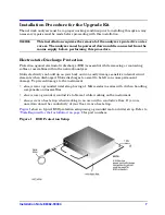
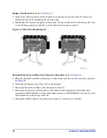
Install the Old Front Panel LED Board onto the New Front Panel
(Refer to
.)
1. Remove the LED board from the old front panel by removing the three retaining screws
(item
①
).
2. Place the LED board in position on the new front panel and attach it with the three screws
(item
①
) removed from the old front panel.
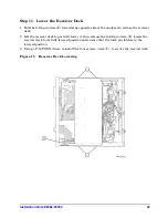
Figure 10 Front Panel LED Board Reinstallation
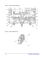
Install the New Couplers on the New Front Panel
1. Place the new couplers onto the new front panel. Orient them the same as the old ones as
shown in
.
2. Install a flange nut (item
③
) removed from the old couplers, onto each new coupler. Using
a 1-inch torque wrench, tighten each flange nut to 72 in-lbs.
3. Reconnect the two cables (item
②
) to the test port couplers that were disconnected on
.
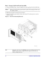
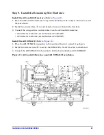
Install the New Front Panel on the Analyzer
.)
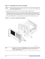
1. Place the new test set deck front panel, with the new LED board and both new couplers
attached, onto the test set deck as shown in
.
2. Using a T-10 TORX driver,
loosely
reinstall the eight screws (items
❶
through
❽
) to secure
the front panel to the test set deck. Torque each of the eight screws to 9 in-lbs in the order
indicated (
❶
through
❽
). This is important to ensure proper alignment.
3. Reconnect the wrapped wire cable (item
①
) to the front-panel LED board.


