


24
User’s Guide
E8362/3/4C Option H85
Example: Making High Power Measurements with Option H85
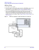
Figure 10
Isolators and Attenuator Connections
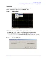
Select Receiver Port Power Ranges
1. Calculate the amount of attenuation needed between the analyzer's coupler and
receivers, so that you do not exceed the optimum receiver power level of –12 dBm.
It will be necessary to take the following into consideration:
• Receiver A will be coupled to the analyzer RF path that could receive power
reflections as high as +10 dBm.
• Receiver B will be coupled to the analyzer RF path that could receive a
maximum of +20 dBm from the DUT.
• Analyzer coupler loss is –13 dB.
• The optimum receiver power level is –12 dBm.
With the previous points in mind, the amount of attenuation can be calculated from the
following equations:
Fix Attenuator
Fix Attenuator
2-Port One Way High
Power Configuration
Booster Amplifier
RF
INPUT
RF
OUTPUT
Coupler
Arm
20 dB
Coupler
Main
Coupler
Output
Fix
Attenuator
CPLR ARM
RCVR A IN
SOURCE OUT
RCVR R1 IN
CPLR THRU
CPLR ARM
RCVR B IN
Isolator
In
Out
SOURCE OUT
CPLR THRU
Receiver Attenuator A
10
dBm
13
dBm
12
dBm
–
(
)
–
–
+
=
Attenuator A
10
dBm
+
=
Receiver Attenuator B
20
dBm
13
dBm
12
dBm
–
(
)
–
–
+
=
Attenuator B
20
dBm
+
=
Содержание E8362
Страница 4: ...iv User sGuide ...
Страница 6: ...Contents 2 User sGuide ...
Страница 7: ...User s Guide 1 E8362 3 4C Option H85 ...
Страница 44: ...38 User s Guide E8362 3 4C Option H85 Agilent Support and Assistance ...


