


8
Installation Note E8356-90052
Step 2.
Replace the A12 Source Assembly (E8356A Only)
This step is necessary only for the E8356A network analyzer. If installing an upgrade kit for
the E8357A network analyzer, proceed to Step 3.
Remove the Outer and Inner Covers from the Analyzer
Refer to
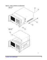
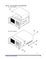
Remove the Outer Cover
CAUTION
This procedure is best performed with the analyzer resting on its front handles
in the vertical position. Do not place the analyzer on its front panel without the
handles. This will damage the front panel assemblies.
1. Disconnect the power cord (if it has not already been disconnected).
2. With a T-20 TORX driver, remove the strap handles (item
①
) by loosening the screws
(item
②
) on both ends until the handle is free of the analyzer.
3. With a T-20 TORX driver, remove the four rear panel feet (item
③
) by removing the center
screws (item
④
).
4. Slide the four bottom feet (item
⑤
) off the cover.
5. Slide the cover off of the frame.
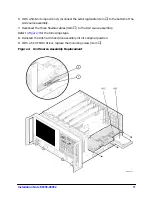
Remove the Inner Cover
1. With a T-10 TORX driver, remove the 15 screws (item
⑥
).
2. Lift off the cover.