


24
Operation and Service Guide
Service
Service
Service instructions consist of principles of operation, troubleshooting, and
repairs.
Principles of Operation
The A1 Bulkhead assembly provides a 50 ohm load to the RF signal applied
to the power sensor. A diode assembly in the bulkhead rectifies the applied
RF to produce a dc voltage which varies with the RF power across the 50
ohm load. Thus the voltage varies with the RF power dissipated in the load.
With maximum specified RF power (100 mW) the dc voltage is approxi-
mately 1V.
The low-level dc voltage from the bulkhead assembly must be amplified
before it can be transferred on standard cables to the power meter. The
amplification is provided by an input amplifier assembly which consists of a
chopper (sampling gate) and an input amplifier. The chopper circuit converts
the dc voltage to an ac voltage. To do this, the chopper uses two field effect
transistors (FETs), A2Q1 and A2Q2, controlled by a 440 Hz square wave
generated by the power meter. The amplitude of the sampling gate output
(drain of A2Q1, source of A2Q2) is a 440 Hz square wave which varies with
the RF power input. The 440 Hz ac output is applied to the input amplifier
A2Q3 which provides the input to the first amplifier stage in the power
meter.
The E44XX-Series power meter automatically detects when an E44XX-
Series power sensor is connected and downloads the correction data from the
sensor’s EEPROM. This configures the power meter to operate over the +20
dBm to
−
70 dBm power range with that particular sensor’s unique correction
data applied.
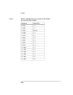
Troubleshooting
Troubleshooting information is intended to first isolate the power sensor, the
cable, or the power meter as the defective component. When the power sen-
sor is isolated, a “Restored Sensor Module” must be used for repair. See
Table 6.
Содержание E4412A
Страница 6: ...4 Safety Information ...
Страница 7: ...5 1 Operation and Service Guide ...
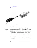
Страница 24: ...22 Operation and Service Guide Replaceable Parts Figure 3 Illustrated Parts Break down ...
Страница 30: ...28 Operation and Service Guide Service ...


