


E2730A VXI RF TUNER
OPERATION
3-1
SECTION 3
OPERATION
3.1 INTRODUCTION
The E2730A VXI RF Tuner is controlled using either word serial
commands or binary commands via the VXI Interface. In addition, the
RS-232 port (AUX, located on the front panel) also accepts the same
mnemonics that are used with the word serial VXI commands. The
following paragraphs provide the details required for the system integrator
to access, control, and monitor the tuner's operation. The following
discussions assume that the system integrator is familiar with the rules and
guidelines contained in the VXIbus Specification and RS-232 interface
specifications. A copy of the VXIbus Specification can be requested by
writing to:
VXIbus Consortium, Inc.
P.O. Box 1736
Vancouver, WA 98668 U.S.A.
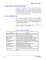
3.2 INDICATORS
All tuner indicators are located on the front panel. Two LEDs are
provided for monitoring the operating status of the unit. The following
paragraphs further explain the function of each LED. The E2730A has no
front panel controls.
3.2.1 RUN INDICATOR, GREEN LED
This green LED illuminates approximately one second after power is
applied to the tuner, indicating that the tuner’s microcontroller is active
and running properly.
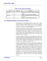
3.2.2 ERR INDICATOR, RED LED
This red LED illuminates when internal diagnostic circuitry detects any of
the following tuner errors:
•
Any Unlocked LO
•
EEPROM Defaulted (illuminate for three seconds only)
Note that the ERR indicator does not indicate the receipt of invalid remote
messages.
Содержание E2730A
Страница 5: ...E2730A VXI RF TUNER iv LIST OF EFFECTIVE PAGES THIS PAGE INTENTIONALLY LEFT BLANK ...
Страница 7: ...E2730A VXI RF TUNER vi REVISION RECORD THIS PAGE INTENTIONALLY LEFT BLANK ...
Страница 12: ...1 i SECTION 1 GENERAL DESCRIPTION ...
Страница 13: ...1 ii THIS PAGE INTENTIONALLY LEFT BLANK ...
Страница 18: ...2 i SECTION 2 INSTALLATION ...
Страница 19: ...2 ii THIS PAGE INTENTIONALLY LEFT BLANK ...
Страница 32: ...3 i SECTION 3 OPERATION ...
Страница 33: ...3 ii THIS PAGE INTENTIONALLY LEFT BLANK ...
Страница 66: ...4 i SECTION 4 REPLACEMENT PARTS LIST ...
Страница 67: ...4 ii THIS PAGE INTENTIONALLY LEFT BLANK ...
Страница 71: ...E2730A VXI RF TUNER 4 4 REPLACEMENT PARTS LIST NOTES ...
Страница 72: ...FP i FOLDOUTS ...
Страница 73: ...FP ii THIS PAGE INTENTIONALLY LEFT BLANK ...


