Page 7 of 9
MSO6104A-01A-S
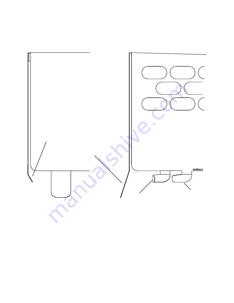
To reinstall the power supply shield
1.
Ensure that tabs and hook legs have not been damaged.
Figure 5
Proper angles for tabs and hook legs.
Angled tabs
Angled hook legs
Damaged hook tab
Proper hook tab
Страница 1: ...CE RETURN USED RETURN CATEGORY ON SITE INVENTORY SCRAP PARTS SCRAP X SERVICE CENTER X SEE TEXT X SEE TEXT AVAILABILITY ALWAYS AGILENT RESPONSIBLE UNTIL ALWAYS AUTHOR DPM PRODUCT LINE 1A ADDITIONAL INFORMATION AGILENT TECHNOLOGIES INC 2007 PRINTED IN U S A March 19 2007 Page 1 of 9 MSO6104A 01A S S E R V I C E N O T E Supersedes MSO6104A 01 S MSO6104A 4 16 channel 1 GHz Mixed Signal Oscilloscope Se...
Страница 2: ...m the maintenance Whenever possible perform the procedures with the power cord removed from the oscilloscope WARNING AVOID ELECTRICAL SHOCK Hazardous voltages exist on the LCD assembly and power supply To avoid electrical shock 1 Disconnect the power cord from the oscilloscope 2 Wait at least three minutes for the capacitors in the oscilloscope to discharge before you begin disassembly CAUTION REM...
Страница 3: ... Rotate the handle to the up position as shown 3 Using the T20 TORX driver remove the two screws from the rear of the cabinet 4 Using your thumbs gently push on the rear panel connectors to slide the oscilloscope out of the cabinet Figure 1 Remove the cabinet T 20 Screw T 20 Screw Gently Push on the connectors ...
Страница 4: ...ull back on each side of the shield until the 4 side hook legs clear their slots in the deck WARNING Thin sheet metal parts may have sharp edges Handle with care to avoid injury Figure 2 Release hook legs from deck Pull back Pull back Hook Legs Hook Leg Slot in Deck ...
Страница 5: ...he dielectric insulator tape 1 Turn the shield on it s side as shown 2 Clean the adhesion area on the shield with alcohol Figure 3 Prepare to install insulator 3 Apply the dielectric insulator to the shield ensuring that it is within the tolerances shown Adhesion Area ...
Страница 6: ...Page 6 of 9 MSO6104A 01A S Figure 4 Apply dielectric insulator ...
Страница 7: ...MSO6104A 01A S To reinstall the power supply shield 1 Ensure that tabs and hook legs have not been damaged Figure 5 Proper angles for tabs and hook legs Angled tabs Angled hook legs Damaged hook tab Proper hook tab ...
Страница 8: ...e front of the shield by tilting the shield up Figure 6 Tilt to insert tabs 3 Tilt the shield down and pull back slightly to insert the 4 side hook legs into their deck slots 4 Push the shield forward to lock into place Insert tabs in deck slots Tilt up ...
Страница 9: ...stall the cabinet 1 Slide the oscilloscope into the cabinet until connectors are fully in their openings in the rear panel 2 Replace the two T20 screws shown in Figure 1 on page 3 Run user self test Follow the instructions in the service guide to verify that the instrument passes User Self Test No calibration is required Insert Lock ...