150
Chapter 5 Remote Interface Reference
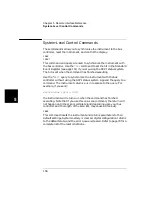
Status System Commands
5
The Operation Status Register
The 3499A/B/C uses only three of the bits in this 16-bit register. Bit 0
indicates the instrument is waiting in the trigger layer (the next trigger
event will advance the scan list). Bit 1 indicates the instrument is
waiting in the arm layer (the next trigger event will move the instrument
to the trigger layer). Bit 4 indicates a scan has started.
STATus
:OPERation:CONDition?
Since the condition register is updated in real time, you will generally
not use this register query. For example, bit 4 will never appear to be set
since you cannot read the register at the time a scan starts.
STATus
:OPERation[:EVENt]?
This query returns the binary weighted sum of the values in the event
register. These bits are latched from the condition register and indicate
that an event has occurred (at some time since the register was last
cleared).
Sending this query clears all bits in the register.
STATus
:OPERation:ENABle <unmask>
:OPERation:ENABle?
These commands work with the enable register. The enable register is a
mask used to determine which bits in the event register can be recorded
in the OPR summary bit (bit 7) of the Status Byte register.
unmask can range from 0 to 16348, but is only applicable to the
3499A/B/C with the values 1, 2, and 16. For example sending:
STATus:OPERation:ENABle 16
sets the OPR summary bit in the Status Byte Register to be true (1)
when a scan has started.
The query form of this command returns a decimal weighted value
indicating the currently set bits in this register.
STATus
:PRESet
This command clears the Operation Status Register enable register bits.
All Enable bits are set to 0. This command does not affect the other
register groups and does not clear the event register.
Содержание Agilent 3499A
Страница 13: ...1 1 Quick Start ...
Страница 27: ...2 2 Front Panel Operation ...
Страница 55: ...3 3 System Overview ...
Страница 77: ...4 4 Features and Functions ...
Страница 113: ...5 5 Remote Interface Reference ...
Страница 164: ...164 5 ...
Страница 165: ...6 6 Error Messages ...
Страница 173: ...7 7 Plug in Modules ...
Страница 256: ...256 Chapter 7 Plug in Modules 44475A Breadboard Module 7 ...
Страница 261: ...261 Chapter 7 Plug in Modules 44476B Microwave Switch Module 4 7 The 44476B is shown below ...
Страница 268: ...268 Chapter 7 Plug in Modules 44478A B 1 3 GHz Dual 4 to 1 MUX Modules 7 The 44478A B is shown below ...
Страница 286: ...286 Chapter 7 Plug in Modules Terminals and Connections Information 7 ...
Страница 288: ...288 7 ...
Страница 289: ...8 8 Application Programs ...
Страница 299: ...9 9 Specifications ...
Страница 343: ...343 Chapter 9 Specifications 44475A Breadboard Module 4 9 ...


