


Index
Index
Index-1
Symbols
+5 V digital supply
theory of operation
,
Numerics
10 MHz HI OUT Waveform from
A14J1
,
10 MHz precision reference
assembly replacement
,
100 kHz pulses
,
1st LO signal at sampler/mixer
,
25 MHz HI OUT Waveform from
A14J1
,
2nd IF (4 kHz) signal locations
,
2nd LO locations
,
2ND LO waveforms
,
4 kHz signal check
,
4 MHz REF signal check
,
4 MHz reference signal
,
60 MHz HI OUT Waveform from
A14J1
,
75 ohm impedance option
,
8753E adjustments
,
8753ES block diagram
,
A
A and B input traces check
,
A1/A2 front panel
troubleshooting
,
A10 assembly signals required
,
A10 check by substitution or
signal examination
,
A10 digital IF
,
,
digital control
A11 input signals
A11 phase lock
,
source
,
A11 phase lock and A3 source
check
,
A11 phase lock check
,
A12 digital control signals check
,
A12 reference
,
source
,
A12 reference check
A13 frac-N analog
source
,
A13/A14 Fractional-N Check
,
A14 Divide-by-N Circuit Check
,
A14 Frac-N digital source
,
A14 fractional-N (digital)
A14 generated digital control
signals
A14 VCO exercise
,
A14-to-A13 digital control signals
check
A15 preregulator
check
theory of operation
,
A15W1 plug detail
,
A16 rear panel
digital control
A18 display
digital control
power
A19 GSP digital control
A2 front panel processor digital
control
,
A21 test port coupler
,
A22 test port coupler
,
A23 LED front panel
,
A24 transfer switch
A25 test set interface
,
A27 inverter digital control
,
A3 source
and A11 phase lock check
external source mode
frequency offset
,
harmonic analysis
,
high band theory
,
low band theory
,
operation in other modes
,
source
,
super low band theory
,
theory of operation
,
tuned receiver mode
,
A4 sampler/mixer
A4 sampler/mixer check
A5 sampler/mixer
A6 sampler/mixer
A7 pulse generator check
,
A7 pulse generator source
,
A8 post regulator
air flow detector
,
display power
,
fuses and voltages
,
green LEDs
probe power
shutdown circuit
,
test points
,
theory of operation
,
variable fan circuit
A9 CPU
digital control
operation check
abbreviation definitions
ABUS Cor.
,
ABUS node 16 for power check
,
ABUS test
,
accessories
error message check
inspection
,
troubleshooting
,
troubleshooting chapter
,
accuracy of frequency adjustment
,
adapters
,
ADC Hist.
,
ADC Lin.
ADC main
,
ADC offset correction constants
adjustment
,
ADC Ofs.
ADC Ofs. Cor.
,
ADD
,
addresses for GPIB systems
adjustment
A9 switch positions
,
ADC offset correction constants
(test 52)
,
analog bus correction constants
(test 46)
,
cavity oscillator frequency
correction constants (test
54)
fractional-N frequency range
,
fractional-N spur avoidance and
FM sideband
frequency accuracy
,
high/low band transition
IF amplifier correction
constants (test 51)
,
initialize EEPROM’s (test 58)
,
option numbers correction
constants (test 56)
,
RF output power correction
constants (test 47)
,
sampler magnitude and phase
correction constants (test
53)
sequences for mechanical
adjustments
,
serial number correction
constants (test 55)
,
source default correction
constants (test 44)
,
source pretune correction
constants (test 48)
,
source pretune default
correction constants (test
45)
Содержание 8753ES
Страница 14: ...Contents xiv Contents ...
Страница 15: ...1 1 1 Service Equipment and Analyzer Options ...
Страница 26: ...1 12 Chapter1 Service Equipment and Analyzer Options Service and Support Options ...
Страница 27: ...2 1 2 System Verification and Performance Tests ...
Страница 202: ...2 176 Chapter2 System Verification and Performance Tests Agilent 8753ET Performance Test Records ...
Страница 203: ...3 1 3 Adjustments and Correction Constants ...
Страница 262: ...3 60 Chapter3 Adjustments and Correction Constants Sequences for Mechanical Adjustments ...
Страница 263: ...4 1 4 Start Troubleshooting Here ...
Страница 297: ...5 1 5 Power Supply Troubleshooting ...
Страница 305: ...Chapter 5 5 9 Power Supply Troubleshooting If the Red LED of the A15 Is ON Figure 5 5 Power Supply Cable Locations ...
Страница 317: ......
Страница 318: ...6 1 6 Digital Control Troubleshooting ...
Страница 337: ...6 20 Chapter6 Digital Control Troubleshooting GPIB Failures ...
Страница 338: ...7 1 7 Source Troubleshooting ...
Страница 369: ...7 32 Chapter7 Source Troubleshooting Source Group Troubleshooting Appendix ...
Страница 370: ...8 1 8 Receiver Troubleshooting ...
Страница 381: ...8 12 Chapter8 Receiver Troubleshooting Troubleshooting When One or More Inputs Look Good ...
Страница 382: ...9 1 9 Accessories Troubleshooting ...
Страница 389: ...9 8 Chapter9 Accessories Troubleshooting Inspect the Error Terms ...
Страница 390: ...10 1 10 Service Key Menus and Error Messages ...
Страница 439: ...10 50 Chapter10 Service Key Menus and Error Messages Error Messages ...
Страница 440: ...11 1 11 Error Terms ...
Страница 451: ...11 12 Chapter11 Error Terms Error Correction ...
Страница 452: ...12 1 12 Theory of Operation ...
Страница 461: ...12 10 Chapter12 Theory of Operation Digital Control Theory Figure 12 3 Digital Control Group Simplified Block Diagram ...
Страница 482: ...13 1 13 Replaceable Parts ...
Страница 487: ...13 6 Chapter13 Replaceable Parts Ordering Information Figure 13 1 Module Exchange Procedure ...
Страница 490: ...Chapter 13 13 9 Replaceable Parts Replaceable Part Listings This page intentionally left blank ...
Страница 492: ...Chapter 13 13 11 Replaceable Parts Replaceable Part Listings Figure 13 2 8753ET Major Assemblies Top ...
Страница 494: ...Chapter 13 13 13 Replaceable Parts Replaceable Part Listings Figure 13 3 8753ES Major Assemblies Top ...
Страница 498: ...Chapter 13 13 17 Replaceable Parts Replaceable Part Listings This page intentionally left blank ...
Страница 500: ...Chapter 13 13 19 Replaceable Parts Replaceable Part Listings Figure 13 7 8753ET Cables Top ...
Страница 502: ...Chapter 13 13 21 Replaceable Parts Replaceable Part Listings Figure 13 8 8753ES Cables Top ...
Страница 504: ...Chapter 13 13 23 Replaceable Parts Replaceable Part Listings This page intentionally left blank ...
Страница 506: ...Chapter 13 13 25 Replaceable Parts Replaceable Part Listings Figure 13 10 8753ET Cables Bottom ...
Страница 508: ...Chapter 13 13 27 Replaceable Parts Replaceable Part Listings Figure 13 11 8753ES Cables Bottom ...
Страница 510: ...Chapter 13 13 29 Replaceable Parts Replaceable Part Listings Figure 13 12 8753ET Cables Front 8753ET Option 004 ...
Страница 512: ...Chapter 13 13 31 Replaceable Parts Replaceable Part Listings Figure 13 13 8753ES Cables Front ...
Страница 514: ...Chapter 13 13 33 Replaceable Parts Replaceable Part Listings Figure 13 14 8753ET ES Cables Rear ...
Страница 518: ...Chapter 13 13 37 Replaceable Parts Replaceable Part Listings Figure 13 17 8753ET ES Front Panel Assembly Outside ...
Страница 520: ...Chapter 13 13 39 Replaceable Parts Replaceable Part Listings Figure 13 18 8753ET ES Front Panel Assembly Inside ...
Страница 522: ...Chapter 13 13 41 Replaceable Parts Replaceable Part Listings Figure 13 19 8753ET Rear Panel Assembly ...
Страница 524: ...Chapter 13 13 43 Replaceable Parts Replaceable Part Listings Figure 13 20 8753ES Rear Panel Assembly ...
Страница 526: ...Chapter 13 13 45 Replaceable Parts Replaceable Part Listings Figure 13 21 8753ET ES Rear Panel Assembly Option 1D5 ...
Страница 528: ...Chapter 13 13 47 Replaceable Parts Replaceable Part Listings Figure 13 22 8753ET ES Hardware Top ...
Страница 538: ...Chapter 13 13 57 Replaceable Parts Replaceable Part Listings Figure 13 31 8753ET ES Chassis Parts Outside ...
Страница 544: ...14 1 14 Assembly Replacement and Post Repair Procedures ...
Страница 550: ...Chapter 14 14 7 Assembly Replacement and Post Repair Procedures Covers Figure 14 2 Covers ...
Страница 552: ...Chapter 14 14 9 Assembly Replacement and Post Repair Procedures Front Panel Assembly Figure 14 3 Front Panel Assembly ...
Страница 558: ...Chapter 14 14 15 Assembly Replacement and Post Repair Procedures Rear Panel Assembly Figure 14 6 Rear Panel Assembly ...
Страница 562: ...Chapter 14 14 19 Assembly Replacement and Post Repair Procedures A3 Source Assembly Figure 14 8 A3 Source Assembly ...
Страница 568: ...Chapter 14 14 25 Assembly Replacement and Post Repair Procedures A9 CPU Board Figure 14 11 A9 CPU Board ...
Страница 570: ...Chapter 14 14 27 Assembly Replacement and Post Repair Procedures A9BT1 Battery Figure 14 12 A9BT1 Battery ...
Страница 572: ...Chapter 14 14 29 Assembly Replacement and Post Repair Procedures A15 Preregulator Figure 14 13 A15 Preregulator ...
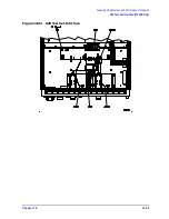
Страница 588: ...Chapter 14 14 45 Assembly Replacement and Post Repair Procedures A23 LED Board 8753ES Only Figure 14 20 A23 LED Board ...
Страница 597: ...14 54 Chapter14 Assembly Replacement and Post Repair Procedures Post Repair Procedures ...
Страница 598: ...15 1 15 Safety and Regulatory Information ...


