


14-38
Chapter 14
Assembly Replacement and Post-Repair Procedures
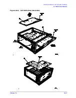
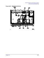
A20 Disk Drive Assembly
A20 Disk Drive Assembly Replacement
1. Attach the plug (item 4) to the replacement disk drive.
2. Attach the disk drive bracket to the replacement disk drive as shown. Leave the three
screws loose in case the disk drive’s position needs to be adjusted.
NOTE
Place the disk drive on a horizontal and flat surface when attaching the
bracket. This minimizes distortion of the disk drive.
3. Connect the disk drive ribbon cable to the replacement disk drive.
NOTE
In steps 3 and 5, make sure that the connector-contacts on both the disk drive
and the CPU touch the ribbon cable contact areas (the ribbon-cable contact
areas must face the contacts in the disk drive and CPU connectors). Also
assure that the connector is properly locked by gently pushing down on the
ends of the connector body.
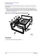
4. Slide the disk drive assembly into the analyzer. Align the disk drive door with the
opening in the front panel. Attach it to the analyzer frame using the four screws from
step 3 of the “Removal” procedure.
5. Route the ribbon cable through the side access hole. Avoid twisting the cable: duplicate
the original folds made to the cable. Connect the disk drive cable to the CPU board.
Refer to item 1 in
. Secure the ribbon cable to its clamp on the test set deck.
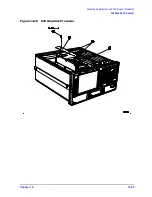
6. Remove the trim strip from the top of the front panel.
7. Remove the top left screw located under the trim strip.
8. Tighten the three screws (item 3) that fasten the disk drive to the bracket. The top
front-most screw is accessed through the exposed screw-hole under the trim strip.
Содержание 8753ES
Страница 14: ...Contents xiv Contents ...
Страница 15: ...1 1 1 Service Equipment and Analyzer Options ...
Страница 26: ...1 12 Chapter1 Service Equipment and Analyzer Options Service and Support Options ...
Страница 27: ...2 1 2 System Verification and Performance Tests ...
Страница 202: ...2 176 Chapter2 System Verification and Performance Tests Agilent 8753ET Performance Test Records ...
Страница 203: ...3 1 3 Adjustments and Correction Constants ...
Страница 262: ...3 60 Chapter3 Adjustments and Correction Constants Sequences for Mechanical Adjustments ...
Страница 263: ...4 1 4 Start Troubleshooting Here ...
Страница 297: ...5 1 5 Power Supply Troubleshooting ...
Страница 305: ...Chapter 5 5 9 Power Supply Troubleshooting If the Red LED of the A15 Is ON Figure 5 5 Power Supply Cable Locations ...
Страница 317: ......
Страница 318: ...6 1 6 Digital Control Troubleshooting ...
Страница 337: ...6 20 Chapter6 Digital Control Troubleshooting GPIB Failures ...
Страница 338: ...7 1 7 Source Troubleshooting ...
Страница 369: ...7 32 Chapter7 Source Troubleshooting Source Group Troubleshooting Appendix ...
Страница 370: ...8 1 8 Receiver Troubleshooting ...
Страница 381: ...8 12 Chapter8 Receiver Troubleshooting Troubleshooting When One or More Inputs Look Good ...
Страница 382: ...9 1 9 Accessories Troubleshooting ...
Страница 389: ...9 8 Chapter9 Accessories Troubleshooting Inspect the Error Terms ...
Страница 390: ...10 1 10 Service Key Menus and Error Messages ...
Страница 439: ...10 50 Chapter10 Service Key Menus and Error Messages Error Messages ...
Страница 440: ...11 1 11 Error Terms ...
Страница 451: ...11 12 Chapter11 Error Terms Error Correction ...
Страница 452: ...12 1 12 Theory of Operation ...
Страница 461: ...12 10 Chapter12 Theory of Operation Digital Control Theory Figure 12 3 Digital Control Group Simplified Block Diagram ...
Страница 482: ...13 1 13 Replaceable Parts ...
Страница 487: ...13 6 Chapter13 Replaceable Parts Ordering Information Figure 13 1 Module Exchange Procedure ...
Страница 490: ...Chapter 13 13 9 Replaceable Parts Replaceable Part Listings This page intentionally left blank ...
Страница 492: ...Chapter 13 13 11 Replaceable Parts Replaceable Part Listings Figure 13 2 8753ET Major Assemblies Top ...
Страница 494: ...Chapter 13 13 13 Replaceable Parts Replaceable Part Listings Figure 13 3 8753ES Major Assemblies Top ...
Страница 498: ...Chapter 13 13 17 Replaceable Parts Replaceable Part Listings This page intentionally left blank ...
Страница 500: ...Chapter 13 13 19 Replaceable Parts Replaceable Part Listings Figure 13 7 8753ET Cables Top ...
Страница 502: ...Chapter 13 13 21 Replaceable Parts Replaceable Part Listings Figure 13 8 8753ES Cables Top ...
Страница 504: ...Chapter 13 13 23 Replaceable Parts Replaceable Part Listings This page intentionally left blank ...
Страница 506: ...Chapter 13 13 25 Replaceable Parts Replaceable Part Listings Figure 13 10 8753ET Cables Bottom ...
Страница 508: ...Chapter 13 13 27 Replaceable Parts Replaceable Part Listings Figure 13 11 8753ES Cables Bottom ...
Страница 510: ...Chapter 13 13 29 Replaceable Parts Replaceable Part Listings Figure 13 12 8753ET Cables Front 8753ET Option 004 ...
Страница 512: ...Chapter 13 13 31 Replaceable Parts Replaceable Part Listings Figure 13 13 8753ES Cables Front ...
Страница 514: ...Chapter 13 13 33 Replaceable Parts Replaceable Part Listings Figure 13 14 8753ET ES Cables Rear ...
Страница 518: ...Chapter 13 13 37 Replaceable Parts Replaceable Part Listings Figure 13 17 8753ET ES Front Panel Assembly Outside ...
Страница 520: ...Chapter 13 13 39 Replaceable Parts Replaceable Part Listings Figure 13 18 8753ET ES Front Panel Assembly Inside ...
Страница 522: ...Chapter 13 13 41 Replaceable Parts Replaceable Part Listings Figure 13 19 8753ET Rear Panel Assembly ...
Страница 524: ...Chapter 13 13 43 Replaceable Parts Replaceable Part Listings Figure 13 20 8753ES Rear Panel Assembly ...
Страница 526: ...Chapter 13 13 45 Replaceable Parts Replaceable Part Listings Figure 13 21 8753ET ES Rear Panel Assembly Option 1D5 ...
Страница 528: ...Chapter 13 13 47 Replaceable Parts Replaceable Part Listings Figure 13 22 8753ET ES Hardware Top ...
Страница 538: ...Chapter 13 13 57 Replaceable Parts Replaceable Part Listings Figure 13 31 8753ET ES Chassis Parts Outside ...
Страница 544: ...14 1 14 Assembly Replacement and Post Repair Procedures ...
Страница 550: ...Chapter 14 14 7 Assembly Replacement and Post Repair Procedures Covers Figure 14 2 Covers ...
Страница 552: ...Chapter 14 14 9 Assembly Replacement and Post Repair Procedures Front Panel Assembly Figure 14 3 Front Panel Assembly ...
Страница 558: ...Chapter 14 14 15 Assembly Replacement and Post Repair Procedures Rear Panel Assembly Figure 14 6 Rear Panel Assembly ...
Страница 562: ...Chapter 14 14 19 Assembly Replacement and Post Repair Procedures A3 Source Assembly Figure 14 8 A3 Source Assembly ...
Страница 568: ...Chapter 14 14 25 Assembly Replacement and Post Repair Procedures A9 CPU Board Figure 14 11 A9 CPU Board ...
Страница 570: ...Chapter 14 14 27 Assembly Replacement and Post Repair Procedures A9BT1 Battery Figure 14 12 A9BT1 Battery ...
Страница 572: ...Chapter 14 14 29 Assembly Replacement and Post Repair Procedures A15 Preregulator Figure 14 13 A15 Preregulator ...
Страница 588: ...Chapter 14 14 45 Assembly Replacement and Post Repair Procedures A23 LED Board 8753ES Only Figure 14 20 A23 LED Board ...
Страница 597: ...14 54 Chapter14 Assembly Replacement and Post Repair Procedures Post Repair Procedures ...
Страница 598: ...15 1 15 Safety and Regulatory Information ...


