Agilent Technologies 5062-8218 Скачать руководство пользователя страница 4

4

Installation Note 5967-8554

Tools Required

4-mm hex (Allen) wrench

9/16-inch nut driver

Needle-nose pliers (2 pairs required)

T-15 TORX screwdriver

T-10 TORX screwdriver

NOTE

If the spectrum analyzer firmware is dated prior to 27.10.92 (October 27, 1992),
the spectrum analyzer firmware must be replaced with the firmware in the
firmware installation kit. To determine the firmware date on the analyzer, turn
the analyzer power off, then the analyzer power on. The firmware date is
displayed on the analyzer screen. The firmware is displayed in a day.month.year
format. See Contacting Agilent Technologies for details.

WARNING

Before disassembling the instrument, turn the power switch OFF and
unplug the analyzer. Failure to unplug the analyzer can result in
personal injury.

CAUTION

Electrostatic discharge (ESD) can damage or destroy electronic
components. All work on electronic assemblies should be performed at a
static-safe work station. Refer to the installation and verification manual
for your spectrum analyzer for information about a static-safe work
station and static-safe accessories.

Procedure

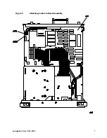
Removing the Instrument Cover

1. Disconnect the analyzer from ac power.

CAUTION

To prevent damage to the front panel, place a soft cloth or towel between the work
surface and the front panel.

2. Carefully place the analyzer on the work surface with the front panel facing down.

3. Remove the four screws and washers attaching the instrument cover to the rear frame.

4. Unscrew, but do not remove, the four rear-feet screws, using a 4-mm hex wrench.

Содержание 5062-8218

Страница 1: ...Part Number 5967 8554 Supersedes 5962 5078 Printed in USA September 2000 Installation Note Time Gated Spectrum Analyzer Capability Installation Kit 5062 8218 ...

Страница 2: ...d to this material including but not limited to the implied warranties of merchantability and fitness for a particular purpose Agilent Technologies shall not be liable for errors contained herein or for incidental or consequential damages in connection with the furnishing performance or use of this material Copyright Agilent Technologies Inc 2000 ...

Страница 3: ...00 9999A99999 0000U00000 9999U99999 To Be Performed By Agilent Technologies Service Center Only Estimated Installation Time 1 2 Hour Estimated Verification Time 1 Hour Item Quantity Description Part Number 1 2 Nut hex 15 32 32 0590 1251 2 1 Cable BNC m to m 8120 2682 3 1 Option 105 product note 5960 2555 4 2 Adapters BNC female to male right angle 1250 0076 5 1 Cable BNC f to SMB f gate in 08591 6...

Страница 4: ...wer switch OFF and unplug the analyzer Failure to unplug the analyzer can result in personal injury CAUTION Electrostatic discharge ESD can damage or destroy electronic components All work on electronic assemblies should be performed at a static safe work station Refer to the installation and verification manual for your spectrum analyzer for information about a static safe work station and static...

Страница 5: ...s attaching the dual I O to the rear panel 8 Remove dual I O connector board from the instrument by pulling up on the board 9 Remove three screws on each side of the rear panel and pull the rear panel gently away from the instrument a few centimeters 10 Remove the plugs from the Gate Trigger In and Gate Out holes on the analyzer rear panel Use one pair of long needle nose pliers to compress the ba...

Страница 6: ... rear panel GATE OUTPUT 2 opening Use a hex nut to attach the cable to the rear panel Tighten the hex nut with the hex wrench 13 Remove the 4 screws attaching the Dual I O interconnect board A40 to the CPU and remove the I O board 14 Route the SMB cable ends to enable them to attach to A16J501 and A16J500 NOTE If J501 and J500 do not exist on the CPU you will need to order a CPU Board Kit Refer to...

Страница 7: ...Installation Note 5967 8554 7 Figure 3 Attaching Cables to Board Assembly ...

Страница 8: ...t bind between the instrument cover and the analyzer internal assemblies 20 Carefully place the analyzer on the work surface with the front panel facing down 21 Replace the instrument cover assembly The seam of the cover should be on the bottom side of the analyzer 22 Tighten the four rear feet screws with a 4 mm hex wrench 23 Replace the four screws and washers attaching the instrument cover asse...

Отзывы: