


08757-90195
37
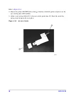
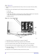
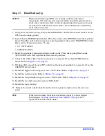
Step 13. Install the Keypad Board
Refer to
Figure 13-1
.
1. Remove the detector interface connector cables (item
①
) from the old front panel and place
them on the new front sub-panel (08757-00071). Orient the notch, on the black portion of
the connectors, down and secure the connectors using hex nut (0535-0031).
2. Select the front panel overlay required for your instrument configuration; four have been
provided. Before you remove the adhesive backing, place the overlay into position and
verify the alignment of the connectors. The edge of the overlay should extend evenly
beyond the edges of the sub-panel. If necessary, loosen the connector nuts and adjust the
connector positions slightly.
3. Peel off the adhesive backing, carefully align the corners, and attach the label to the new
front sub-panel. Rub the label to make sure it adheres securely to the sheet metal.
4. Option 002 has an RF connector (item
②
) on the front panel. Remove the RF connector
from the old front panel and install it on the new front panel.
Figure 13-1 Keypad Board
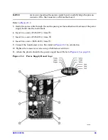
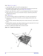
5. Insert the new RPG assembly (1990-1525) with a washer (2190-0016) onto the new front
panel (item
③
). Orient the cable toward the top of the board. Add another washer and a
nut (2950-0043).
6. Place the new main keypad rubber (08757-40017) onto the new keypad board
(08757-60149).
Содержание 08757-60159
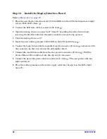
Страница 43: ...08757 90195 43 Figure 16 1 Display Interface Board...
Страница 46: ...46 08757 90195...


