background image

C h a p t e r   3   —   P l a c i n g   y o u r   O r i g i n a l s 

37

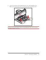
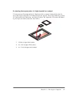
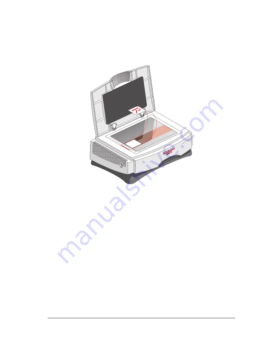
S c a n n i n g   a n   O r i g i n a l   i n   H i g h - R e s o l u t i o n   O u t p u t 

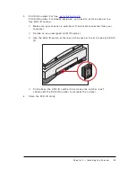
1 .  

O p e n  t h e  d o c u m e n t  c o v e r  o f  t h e  s c a n n e r . 

2 .  

C e n t e r  t h e  o r i g i n a l  f a c e  d o w n  o n  t h e  r e f l e c t i v e  g l a s s  p l a t e  i n  t h e  a r e a 
i n d i c a t e d  b y  t h e  h i g h - r e s o l u t i o n  m a r k . 

3 .  

C l o s e  t h e  d o c u m e n t  c o v e r  o f  t h e  s c a n n e r . 


N o t e :  T h e  i m a g e  q u a l i t y  w i t h  h i g h - r e s o l u t i o n  s c a n n i n g  i s  b e s t  i n  t h e  c e n t e r  o f 
t h e  h i g h - r e s o l u t i o n  s c a n  a r e a . 

Содержание DUOSCAN T2000 XL

Страница 1: ...000 XL for the Apple Macintosh and PC Chapter 3 Placing your Originals This chapter shows you how to place your originals in your DuoScan T2000 XL Appendix A Troubleshooting This appendix can be helpful when you come across problems that you are unable to solve Appendix B Technical Information This appendix provides specifications of your DuoScan T2000 XL Appendix C DuoScan T2000 XL Regulation Com...

Страница 2: ...ntel Corporation Power Macintosh and System 8 are trademarks and Apple and Macintosh are registered trademarks of Apple Computer Incorporated Windows Windows NT and the Windows logo are trademarks or registered trademarks of Microsoft Corporation Other products or company names are trademarks or registered trademarks of their respective holders Copyright 1999 Agfa Gevaert N V All rights reserved A...

Страница 3: ...lation for the Apple Macintosh 17 Which SCSI Interface Card 17 Choosing a SCSI ID Number 17 Connecting the Scanner 20 Testing the Connection 23 Installation for the PC 24 Which SCSI Interface Card 24 Choosing a SCSI ID Number 24 Connecting the Scanner 26 Testing the Connection 33 Performing a Power on Test 34 C h ap t e r 3 P lacin g yo u r O rig in als 3 5 Placing Reflective Originals 36 Scanning...

Страница 4: ...o S can T 2 0 0 0 XL R e g u lat io n C o mp lian ce 5 1 Safety Regulations 51 UL Safety Statement 51 FTZ Bescheinigung des Herstellers Importeurs 51 TÜV Wichtige Sicherheitshinweise 51 Electromagnetic Interference 52 Federal Communications Commission Radio Frequency Interference Statement 52 Canadian Department of Communications 53 ...

Страница 5: ...n transparent originals This allows the scanner to optimize the optical path for both types of originals The dual lens system of the DuoScan T2000 XL offers you the possibility to scan in either high resolution at 2000 dpi or in low resolution at 667 dpi The size of the scan area depends on the resolution type and the mode that you are scanning in Reflective Mode Transparency Mode Low resolution 1...

Страница 6: ...he glass plate holder three single slide holders are supplied with your DuoScan T2000 XL In order to facilitate the scanning of thick originals like magazines and books the document cover adjusts automatically to the thickness of the original If necessary you can remove the document cover of the DuoScan T2000 XL completely by lifting it The originals can be of any type The FotoLook scanning softwa...

Страница 7: ...ner 7 Chapter 1 Preparing the Scanner This chapter assists you in preparing your DuoScan T2000 XL for installation You will find instructions for Unpacking the Scanner Unlocking the Scanner Relocking the Scanner Taking a Closer Look ...

Страница 8: ... when you register you can claim your guarantee and get information on new products and upgrades Unlocking the Scanner The scanner s optical carriage contains all optical components and rides back and forth during the scan An unlocking screw at the left side of your DuoScan T2000 XL holds the carriage in place during shipment You have to remove this screw before powering up the scanner 1 Look for ...

Страница 9: ... you should first relock your scanner This will protect the scanner s optical assembly from possible damage 1 Switch on your scanner and wait until the ready indicator stops blinking 2 Take a coin and turn the screw clockwise in the lock position The screw is fastened your scanner is locked 3 Switch off your scanner ...

Страница 10: ... become familiar with its parts The figure illustrates the locations of the different parts of your DuoScan T2000 XL 1 reflective glass plate 2 removable document cover 3 transparency tray 4 power indicator 5 ready indicator permanent light 6 busy indicator blinking light 7 power switch 8 rulers 9 unlocking screw 10 registration pins ...

Страница 11: ...rts at the rear of your scanner 1 1 2 3 4 5 1 internal terminator switch 2 SCSI ID switch 3 50 pin SCSI connector 4 25 pin SCSI connector 5 power input Glass plate holder and four batch slide holders 4 x 5 inch 60 x 90 mm 35 mm framed and 35 mm strips An optional rail with registration pins is available ...

Страница 12: ...e and Software Requirements Environmental Requirements Precautions Cleaning your Scanner Installation of the Software SCSI Devices Installation for the Apple Macintosh Which SCSI Interface Card Choosing a SCSI ID Number Connecting the Scanner Testing the Connection Installation for the PC Which SCSI Interface Card Choosing a SCSI ID Number Connecting the Scanner Testing the Connection Performing a...

Страница 13: ...olors o 32 MB of RAM 64 MB of RAM is recommended o FotoLook is compatible with all IBM PC s and compatibles capable of running Windows 95 Windows 98 or NT 4 0 for Intel platforms o An ASPI compatible SCSI card In general FotoLook supports all fully WINASPI compatible cards Some SCSI cards require a special SCSI cable e g wide SCSI Contact your supplier for the proper cable v Note Please read the i...

Страница 14: ...or Agfa service representative Precautions For your own safety and that of your equipment respect conscientiously the Environmental Requirements and always take the following precautions C au t io n For the reason of safety besides the personal maintenance mentioned in this Owner s Guide do not try to remove any mechanical parts or any electronic devices If you need service our dealer and service ...

Страница 15: ...on cables for power cables Cleaning your Scanner n In order to maintain the quality of your scanned images regularly clean both glass plates the reflective glass plate and the glass plate holder n Before cleaning switch off the power to the scanner and unplug the cable n Use a damp cloth and a mild detergent or alcohol to clean the surface of the glass plate n When you use sprays directly onto the...

Страница 16: ...d always make sure that your computer and all SCSI devices are switched off If either the computer or any of the devices remains on you could damage the computer or the device A unique SCSI ID number is assigned to each device in the SCSI chain enabling your computer to identify the device it wants to communicate with and the priority of each device C au t io n If two SCSI devices have the same ID...

Страница 17: ...tact your dealer or Agfa service representative Adaptec products are recommended to use together with your DuoScan T1200 v Note If you use an external SCSI card consult the documentation supplied with your interface card This will tell you how to install the card Choosing a SCSI ID Number Before you connect your DuoScan T2000 XL to your Macintosh you have to find out which SCSI ID numbers are alre...

Страница 18: ...our DuoScan T2000 XL is preset to ID 2 4 If SCSI ID number 2 is free go to instruction 5 or If SCSI ID number 2 is already assigned you need to set the scanner to a free SCSI ID number o Make sure that your scanner is switched off and that it is disconnected from your computer o Decide on an unassigned SCSI ID number o Use the SCSI ID switch at the rear of the scanner to set the desired SCSI ID Pu...

Страница 19: ...Chapt er 2 I ns t alling t he Sc anner 19 5 Click OK to close the SCSI ID Checker ...

Страница 20: ...re are no more than two terminators in your SCSI chain one at the beginning and one at the end Some SCSI devices have built in terminators and must therefore be placed at the beginning or at the end of your SCSI chain Please check the documentation of each of your SCSI devices if you are not sure whether the device has a built in terminator Your DuoScan T2000 XL has a built in terminator If your D...

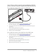
Страница 21: ... end of the SCSI cable to the connector of the scanner 4 Snap the diamond shaped wire clips into the clip brackets to secure the connection 5 Switch on the internal terminator If yo u in st all t h e scan n e r at t h e b e g in n in g o f yo u r S C S I ch ain 1 Connect the 50 pin end of the SCSI cable to the connector that has become available on the last device in the SCSI chain 2 Connect the 2...

Страница 22: ... cable to the scanner 3 Switch off the internal terminator of the scanner 4 Connect the 50 pin end of the SCSI cable the one supplied with your scanner to the other adjacent SCSI device 5 Connect the 25 pin end of the SCSI cable the one supplied with your scanner to the scanner 6 Snap the diamond shaped wire clips into the clip brackets to secure the connection 7 Make sure that the last device in ...

Страница 23: ...test the power indicator light switches on and the ready and busy indicator lights start blinking After the self test the three indicator lights switch on 4 Switch on any other SCSI devices you may have attached and wait for them to start up 5 Switch on your Macintosh As it starts up your Macintosh performs a series of tests to verify the correct system configuration 6 Open the SCSI ID checker 7 V...

Страница 24: ...e The scanner software supplied with DuoScan T2000 XL supports ASPI compatible SCSI interface cards v Note Please check the following documentation n The Read Me file on the PC scanner driver software for up to date information n The documentation supplied with your interface card This will tell you how to install the card Choosing a SCSI ID Number Before you connect your DuoScan HiD to your PC yo...

Страница 25: ... a free SCSI ID number o Make sure your scanner is switched off and is disconnected from your computer o Decide on an unassigned SCSI ID number o Use the SCSI ID switch at the rear of the scanner to set the desired SCSI ID o Push above the SCSI ID number to decrease the number push underneath the SCSI ID number to increase the number 4 Close the SCSI ID utility ...

Страница 26: ... use an external terminator C au t io n For safety reasons never use extension cables for power cables Always make sure that there are no more than two terminators in your SCSI chain one at the beginning and one at the end Some SCSI devices have built in terminators and must therefore be placed at the beginning or end of your SCSI chain Please check the documentation of each of your SCSI devices i...

Страница 27: ... t o be connect ed t o your P C 1 Set the scanner to an unused SCSI ID number between 0 and 6 For more information refer to Choosing a SCSI ID Number 2 Connect the smaller 25 pin end of the SCSI cable to the connector of your PC 3 Connect the larger 50 pin end of the SCSI cable to the connector of your scanner 4 Snap the diamond shaped wire clips into the clip brackets to secure the connection 5 S...

Страница 28: ... the 25 pin end of the SCSI cable to the connector of the scanner 5 Snap the diamond shaped wire clips into the clip brackets to secure the connection 6 Switch on the internal terminator If yo u in st all t h e scan n e r at t h e b e g in n in g o f yo u r S C S I ch ain 1 Set the scanner to an unused SCSI ID number between 0 and 6 For more information refer to Choosing a SCSI ID Number 2 Connect...

Страница 29: ...f these two SCSI devices 3 Connect the free end of this SCSI cable to the scanner 4 Switch off the internal terminator of the scanner 5 Connect the 50 pin end of the SCSI cable the one supplied with your scanner to the other adjacent SCSI device 6 Connect the 25 pin end of the SCSI cable the one supplied with your scanner to the scanner 7 Snap the diamond shaped wire clips into the clip brackets t...

Страница 30: ...Set the scanner to an unused SCSI ID number between 0 and 6 For more information refer to Choosing a SCSI ID Number 2 Connect the larger 50 pin end of the SCSI cable to the connector at the rear of your PC Use the SCSI cable supplied with the scanner 3 Connect the smaller 25 pin end of the SCSI cable to the connector of the scanner 4 Switch on the internal terminator ...

Страница 31: ...e rear of your device Use the cable supplied with the scanner 3 Connect the 25 pin end of the SCSI cable to the scanner 4 Switch on the internal terminator If yo u in st all t h e scan n e r at t h e b e g in n in g o f yo u r S C S I ch ain 1 Set the scanner to an unused SCSI ID number between 0 and 6 For more information refer to Choosing a SCSI ID Number 2 Connect the 50 pin end of the SCSI cab...

Страница 32: ...ion refer to Choosing a SCSI ID Number 3 Connect the 50 pin end of the SCSI cable to the connector at the rear of the adjacent device Use the cable supplied with the scanner 4 Connect the 25 pin end of the cable to the scanner s 25 pin connector 5 Switch off the internal terminator of the scanner 6 Connect the scanner to the next device in the SCSI chain 7 Make sure that the last device in the cha...

Страница 33: ...ht green switches on and the ready and busy indicator lights yellow start blinking After the self test the scanner s power indicator light switches on 4 Switch on any other SCSI devices you may have attached and wait for them to start up 5 Switch on your PC 6 Check if the scanner is present For Windows 95 98 1 Right click My Computer 2 Select properties 3 Select the Device Manager tab Agfa Scanner...

Страница 34: ...icated on the back panel of the scanner corresponds with the voltage in your area If not contact your dealer or Agfa service representative 3 Switch on the scanner The scanner performs a self test during which the power indicator green switches on and the ready and busy indicators both yellow start blinking This takes about half a minute After the self test the three indicators switch on If a malf...

Страница 35: ...ur Originals Placing reflective originals Scanning an original in full area resolution output Scanning an original in high resolution output Placing transparent originals Using the glass plate holder Using the single slide holders Using the batch slide holders ...

Страница 36: ...e original face down on the glass plate with the top side against the left ruler Optical performance for images in full area resolution output on a CCD scanner is always best near the middle of the scan area However the scan quality for specifications is guaranteed for the entire scan area 3 Close the document cover of the scanner v Note The removable document cover makes it possible to scan from ...

Страница 37: ...he document cover of the scanner 2 Center the original face down on the reflective glass plate in the area indicated by the high resolution mark 3 Close the document cover of the scanner v Note The image quality with high resolution scanning is best in the center of the high resolution scan area ...

Страница 38: ... which you put into the transparency tray v Note It is not possible to pull out the transparency tray completely To obtain the best image quality when scanning with the batch slide holders please keep following instructions in mind 1 Insert the rear side the one with the two grooves of the holder into the transparency tray and make sure that the grooves fit inside the tray ...

Страница 39: ... front side of the holder and click it into the transparency tray Make sure that the holder fits into the tray and that it lies perfectly flat C au t io n Do not force down or lean on the transparency tray This can cause serious deformation of the tray ...

Страница 40: ...e holders or with adhesive tape 2 Put the glass plate holder into the transparency tray with the calibration slit to the left side v Note The holders can only be put in the transparency tray with the calibration slits to the left side You can check this also in another way the side with the two little grooves has to be inserted first because the grooves match inside the scanner S canning a t ransp...

Страница 41: ...r 2 Center the original on the glass plate holder so that its top side is directed towards the calibration slit This position guarantees the best quality 3 Fix the single slide holder on the glass plate holder by pushing it firmly down The rear of the holder has a glass adhesive strip so the frame is secured to the glass The holder can still be removed easily 4 Put the glass plate holder into the ...

Страница 42: ...lution output is almost identical to the scanning of originals in full area resolution output The only difference is that for high resolution scanning you have to place the originals in the area indicated by the high resolution mark on the holder 1 35 mm single slide holder 2 6 x 6 cm single slide holder 3 4 x 5 inch single slide holder ...

Страница 43: ... types of batch slide holders with your DuoScan T2000 XL which you have to put into the transparency tray With the batch slide holders many combinations are possible 1 4 x 5 inch batch slide holder 2 6 x 9 cm batch slide holder 3 35 mm framed batch slide holder 4 35 mm strip slide holder ...

Страница 44: ...time Once loaded you put the holder into the transparency tray 1 Put your original in the 35 mm framed batch slide holder Make sure that you put the originals that you want to scan in high resolution output in the area indicated by the high resolution mark on the holder 2 Put the batch slide holder into the transparency tray of the scanner ...

Страница 45: ...ency tray 1 Put your original in the 35 mm strip slide holder Make sure that you put the originals that you want to scan in high resolution output in the area indicated by the high resolution mark on the holder v Note In each strip a margin is provided to position your originals as required 2 Put the strip slide holder into the transparency tray of the scanner ...

Страница 46: ...sure that you put the originals that you want to scan in high resolution output in the area indicated by the high resolution mark on the holder Figure of 6 x 9 cm batch slide holder You can fit the slide frame to your original 6 x 6 cm 6 x 7 cm 6 x 8 cm 6 x 9 cm by adjusting the sliding edge Adjusting the sliding edge before placing the originals results in sharper images because the sliding edge ...

Страница 47: ...canner and unlock properly or call your service representative The ready indicat or light yellow on t he scanner s operat ing panel remains blinking or goes off aft er t he pow er up sequence about half a minut e n A malfunction has been detected by the scanner n Check if you have unlocked the scanner If this can not be the problem please contact your dealer or Agfa service representative The w or...

Страница 48: ...e scanner to identify the device that causes the problem Check if your terminator has been set correctly and restart your workstation n Make sure that your devices have different SCSI numbers If there are devices with the same number assign a different number to each device The scanner report s errors during scanning Apple M acint osh n Switch on the internal terminator If this does not resolve th...

Страница 49: ...x 667 dpi horizontal High resolution 2000dpi x 2000dpi Output resolution 20 4000 ppi A D Conversion 36 bit 12 bit per color Output pixel depth 1 bit output for line art black and white 8 or 12 bit output for gray 24 or 36 bit output for color Max density detected 3 2 D Scanning speed Low resolution TX and RX gray 12 14 ms line TX and RX color 14 16 ms line High resolution TX gray 14 16 ms line RX ...

Страница 50: ...de 6000 hr lifetime 6W Transparency lamp Cold cathode 6000 hr lifetime 6W Warm up time Approximately 35 seconds 180 seconds to reach final image quality Power supply 100 V to 240 V 47 63 Hz Power consumption 40 W Dimensions 493 9 mm 19 inch x 239 3 mm 9 inch x 735 4 mm 29 inch W x H x L Weight 26 kg Acoustic noise 55 dB in continuous mode 45 dB in stand by Interface SCSI 2 interface 1 x 50 pins co...

Страница 51: ...Importeurs Hiermit wird bescheinigt dass der Image Scanner in Übereinstimmung mit den Bestimmungen der vgf 1046 1984 funk entstört ist Der Deutschen Bundespost wurde das inverkehrbringen dieses Gerätes angezeigt und Berechtigung zur Überprüfung der Serie auf Einhaltung der Bestimmungen eingeraumt TÜV Wichtige Sicherheitshinweise n Bitte Lesen Sie sich diese Hinweise sorgfältig durch n Um eine Besc...

Страница 52: ...is equipment has been tested and found to comply with the limits for a Class B digital device pursuant to Part 15 of the FCC Rules These limits are designed to provide reasonable protection against harmful interference when the equipment is operated in a residential installation This equipment generates uses and can radiate radio frequency energy and if not installed and used in accordance with th...

Страница 53: ...emission limits Canadian Department of Communications This digital apparatus does not exceed the Class B limits for radio noise emissions from digital apparatus set out in the Radio Interference Regulations of the Canadian Department of Communications Le présent appareil numérique n émet pas de bruits radioélectriques dépassant les limites applicables aux appareils numériques de la classe B prescr...

Отзывы: