AGFA CR 75.0 Скачать руководство пользователя страница 17

17

2241A EN 20040210

The keypad

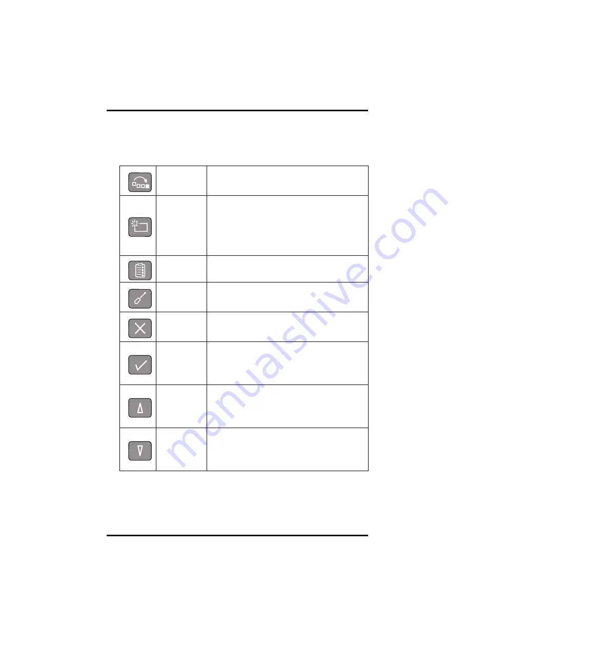
Special functions can be accessed via the keypad. The keypad features the
following keys:

Emergency 
key

To give an image the status ‘emergency’ when it is 
sent to the image processing station.

Erase key

To erase images without digitizing them.
This must be done if:

• an image plate has not been used for more than 

3 days; 

• an image plate has been exposed to an 

exceptionally high X-ray dose.

Key-operator 
key

To access advanced functions (‘key-operator 
functions’).

Service key

To access service-level functions.
Reserved for trained service personnel.

Escape key

To quit the current function or exit a menu without 
saving modifications.

Confirm key

In key-operator mode:

• to select a menu.

• to accept an entry in a menu and go back to 

operator mode.

Up key

• To move the cursor to the previous entry field.

• To scroll upwards.

• To increment the number in a numeric entry 

field.

Down key

• To move the cursor to the next entry field.

• To scroll downwards.

• To decrement the number in a numeric entry 

field.

Содержание CR 75.0

Страница 1: ...CR 75 0 Digitizer Reference manual CR 75 0 MUSICA...

Страница 2: ...e accuracy completeness or usefulness of the information contained in this document and specifically disclaims warranties of suitability for any particular purpose Agfa Gevaert N V shall under no circ...

Страница 3: ...37 Consulting the image transmission queue Queue management 38 Customizing the CR 75 0 Digitizer set up 42 Setting the date and time 48 Sending test images 49 Consulting information on the CR 75 0 50...

Страница 4: ...Compact cassette 91 Safety precautions 92 Description of the ADC Compact cassette 93 Cleaning the image plate 95 Cleaning the cassettes 97 Technical specifications of the cassettes 98 Technical speci...

Страница 5: ...to important safety precautions and introduces the CR 75 0 CR 75 0 intended use CR 75 0 features Safety precautions Safety compliance Operating modes The user interface Switching on the CR 75 0 Switch...

Страница 6: ...IP This device is part of a system consisting of X ray cassettes with erasable phosphor image plates an identification station for the cassettes and a workstation where the resulting digital image inf...

Страница 7: ...ed the cassette is returned to the output buffer to be used for new exposures After a full Digitizer cycle the plate has turned 180 in the cassette Depending on the X ray intensity which has affected...

Страница 8: ...emblies and if the technical data do not permit determining whether the combination with these devices components or assemblies involves hazards you must consult the respective manufacturers to avoid...

Страница 9: ...ndard If required contact your local service organization In order to reduce the risk of electric shock do not remove any covers Caution hot Keep hands clear from the erasure unit Type B equipment Ind...

Страница 10: ...equipment Furthermore all configurations shall comply with the valid version of the system standard IEC 601 1 1 Everybody who connects additional equipment to the signal input part or signal output p...

Страница 11: ...the front left and right door only to solve cassette or image plate jams When you open either of the doors the power supply of all critical components is switched off automatically as a precaution Ob...

Страница 12: ...al safety regulations EN 60601 1 1990 A1 1993 A2 1995 IEC 601 1 1988 A1 1991 A2 1995 IEC 601 1 1 EN 60601 1 1 EN 60601 1 2 1993 UL 2601 1 Second Edition CAN CSA 22 No 601 1 M909 the laser safety regul...

Страница 13: ...5 0 input buffer the other functions of the operator mode can be accessed via the keypad All functions of the operator mode are described in Chapter 2 Basic operation Operator mode Key operator mode T...

Страница 14: ...ettes for erasure Keypad As the handling of the cassettes is fully automated normal operation is a zero button operation The keys on the keypad are only used to activate special functions such as read...

Страница 15: ...15 2241A EN 20040210 Cassette output buffer The cassette output buffer receives cassettes which have been handled by the Digitizer...

Страница 16: ...onsists of a backlit LCD display and 10 keys As the handling of the cassettes is fully automated normal operation is a zero button operation Only when you are performing special functions or in the ev...

Страница 17: ...h X ray dose Key operator key To access advanced functions key operator functions Service key To access service level functions Reserved for trained service personnel Escape key To quit the current fu...

Страница 18: ...d To move the entry position in a numerical entry field from right to left To toggle between values in a field Right key To scroll forwards through multiple choices within a field To move the entry po...

Страница 19: ...age processing station 2 Type of message 3 Extra comment or action to take 4 System status READY The CR 75 0 is ready for operation BUSY The CR 75 0 is busy with scanning or erasing ERROR An error has...

Страница 20: ...s menu driven The menu displays the key operator functions the active keys and the service code Identifier of image plate being treated 8 1 8 2 8 3 After image ID data is read During scanning of image...

Страница 21: ...ed Flashing Busy treating image plate Proceed Red Constant Error Check display for messages Refer to General procedure in case of malfunction on page 77 Flashing Locked or warning Power on self test i...

Страница 22: ...to a key command A short beep means that CR 75 0 has accepted the key command and is starting the operation A long beep means that you have pressed a non active key or that the CR 75 0 has rejected t...

Страница 23: ...e them while working with the CR 75 0 You are acquainted with the basic functions of the Digitizer Switching on the CR 75 0 Locate the main switch and place it in position ON After the Digitizer has b...

Страница 24: ...operator mode and displays the main operator screen The status indicator is constant green The CR 75 0 is ready for use If the CR 75 0 displays An error has occurred during the self test Refer to Chap...

Страница 25: ...us indicator at the top of the machine is green and flashing Switching off It is recommended to switch off the CR 75 0 at the end of the day Place the main switch in position OFF Only switch off the C...

Страница 26: ...manual To reset the Digitizer 1 Locate the main switch and place it in position OFF 2 Wait 30 seconds 3 Place the main switch in position ON Never reset the Digitizer to solve a plate or cassette jam...

Страница 27: ...normal conditions and in emergency situations It also treats how to erase an image plate to prevent ghost images caused by previous exposures or by scattered radiation These functions are available i...

Страница 28: ...e 2 Check that the CR 75 0 is ready for operation the CR 75 0 must display the operator screen with Ready or Busy status the status indicator at the top of the CR 75 0 must be constant or flashing gre...

Страница 29: ...is enabled the CR 75 0 transmits the digital image data in blocks of typical 100 lines to the preview station When the CR 75 0 has treated the cassette it displays the operator main screen 4 Remove th...

Страница 30: ...tor screen with Ready or Busy status the status indicator at the top of the CR 75 0 must be constant or flashing green The CR 75 0 is operational if the status field equals READY even if status messag...

Страница 31: ...a in blocks of typical 100 lines to the preview station When the CR 75 0 has read the identification data of the emergency cassette it displays the operator main screen The Digitizer resumes processin...

Страница 32: ...deep layers of the image plate may still retain a latent image after standard erasure Leave the image plate to rest at least one day before re erasing it You can erase image plates which you have give...

Страница 33: ...reen and the status indicator will be green flashing When the CR 75 0 has erased the image plate it displays the operator main screen You can now add exposed cassettes to the batch of cassettes The Di...

Страница 34: ...or erase the image plate To cancel erasing and make a regular scan press the Escape key To erase the image plate press the Confirm key While erasing the CR 75 0 will display When the CR 75 0 has eras...

Страница 35: ...75 0 must display the operator screen with Ready or Busy status the status indicator at the top of the CR 75 0 must be constant or flashing green 2 Place the cassettes in the input buffer The CR 75 0...

Страница 36: ...36 2241A EN 20040210...

Страница 37: ...management Customizing the CR 75 0 Digitizer set up Setting the date and time Sending test images Consulting information on the CR 75 0 Installing a new software version Installing a new language Inst...

Страница 38: ...ueue Consulting the images in the queue To view which images are being transmitted to a certain image processing station 1 In the key operator main menu select Queue management via the Up and Down key...

Страница 39: ...ain menu press the Escape key twice 4 To go to the operator main screen press the Confirm key S Status Meaning Q In queue Image is waiting in queue to be transmitted T Transmitting Image is being tran...

Страница 40: ...sequently do the following 1 In the list of images being sent to the image processing station select the image which you want to delete via the Up and Down keys 2 Press the Erase key The CR 75 0 will...

Страница 41: ...After the image has been erased the Queue management screen is displayed again 4 To return to the list of installed image processing stations press the Escape key 5 To return to the key operator main...

Страница 42: ...main menu select Digitizer set up via the Up and Down keys and confirm The CR 75 0 will display the Digitizer set up menu If you do not press a key within 1 minute the CR 75 0 will exit the key opera...

Страница 43: ...A EN 20040210 2 Select the Image transmission field via the Up and Down keys 3 Enable or disable the image transmission via the Left and Right keys 4 Confirm your choice The operator main screen is di...

Страница 44: ...the Source rerouting field via the Up and Down keys 3 Select the image processing station from which you want to redirect the images via the Left and Right keys You can only redirect the images of on...

Страница 45: ...45 2241A EN 20040210 5 Select the image processing station to which you want to redirect the images via the Left and Right keys 6 Confirm your choice The operator main screen is displayed...

Страница 46: ...Up and Down keys 3 Select the standard 2 s scan mode or the fast 1 s scan mode via the Left and Right keys 4 Confirm your choice The operator main screen is displayed Queue management Digitizer set u...

Страница 47: ...ll exit the key operator mode 2 Select the Audio signal field via the Up and Down keys 3 Enable or disable the audio signals via the Left and Right keys 4 Confirm your choice The operator main screen...

Страница 48: ...tor mode 2 Set the date and time Use the Left and Right keys to select the digit you want to change tab Use the Up and Down keys to set the digit to the desired value inc dec 3 Confirm the date and ti...

Страница 49: ...onfirm The CR 75 0 will display the Send test image menu If you do not press a key within 1 minute the CR 75 0 will exit the key operator mode 2 Select the image processing station to which you want t...

Страница 50: ...Consulting the device settings 1 In the key operator main menu select System info via the Up and Down keys and confirm The CR 75 0 will display the System info menu Queue management Digitizer set up D...

Страница 51: ...press the Escape key twice To go to the operator main screen press the Confirm key Station Device name of CR 75 0 S N Serial number CR 75 0 5145 S N AE title COMMP Software Software version of CR 75 0...

Страница 52: ...d Down keys and confirm The CR 75 0 will display the Network info menu e g Queue management Digitizer set up Date and Time Send test image System info Install Save configuration Fast preview quit ok s...

Страница 53: ...s the following information 3 To return to the key operator main menu press the Escape key twice To go to the operator main screen press the Confirm key Hostname Name of host computer to which CR 75 0...

Страница 54: ...t scanning an image plate If the CR 75 0 is scanning an image plate the status indicator at the top of the machine is green and flashing 2 In the key operator main menu select Install via the Up and D...

Страница 55: ...r first When you open the left front door the power supply of all critical components is switched off automatically 5 Insert the first floppy with the new CR 75 0 software in the disk drive Please ope...

Страница 56: ...py disks After the last floppy the CR 75 0 displays following screen Checking the volume label Volume is label INSTALL SOFTWARE SERVICE XXXXX Please wait copying files to E temp INSTALL SOFTWARE SERVI...

Страница 57: ...atically After 3 minutes it will display You must make new backup files with the machine specific configuration data Extracting E file name to C file name INSTALL SOFTWARE SERVICE XXXXX SW successfull...

Страница 58: ...e floppy from the disk drive and label it with the data from the screen 14 Store the CR 75 0 software floppies and the backup floppy in the storage box 15 Close the front doors The CR 75 0 will restar...

Страница 59: ...g an image plate If the CR 75 0 is scanning an image plate the status indicator at the top of the machine is green and flashing 2 In the key operator main menu select Install via the Up and Down keys...

Страница 60: ...t front door first When you open the left front door the power supply of all critical components is switched off automatically 5 Insert the floppy with the new language files in the disk drive Please...

Страница 61: ...ve and press the Confirm key The CR 75 0 will display copying A file name to C file name INSTALL LANGUAGE SERVICE XXXXX Language successfully loaded Please remove the floppy and press ok INSTALL LANGU...

Страница 62: ...ep 10 If you want to change the language press the Confirm key The CR 75 0 will display 9 Select the desired language from the list via the Up and Down keys and confirm your choice The CR 75 0 will di...

Страница 63: ...and label it with the data from the screen 14 Store the CR 75 0 language floppy and the backup floppy in the storage box 15 Close the front doors The CR 75 0 will restart automatically After start up...

Страница 64: ...0 is not scanning an image plate If the CR 75 0 is scanning an image plate the status indicator at the top of the machine is green and flashing 2 In the key operator main menu select Install via the...

Страница 65: ...t front door first When you open the left front door the power supply of all critical components is switched off automatically 5 Insert the floppy with the new CPF files in the disk drive Please open...

Страница 66: ...and press the Confirm key 8 Press the Confirm key to activate the new CPF copying file name INSTALL CONFIGURATION SERVICE XXXXX Please remove the floppy and press cancel ok INSTALL CONFIGURATION SERV...

Страница 67: ...offers you the possibility to change the IP address of the CR 75 0 10 You have the choice whether or not to change the IP address To keep the current IP address press the Confirm key To change the IP...

Страница 68: ...0 will start copying the machine specific configuration data while displaying the Save configuration screen Initializing new station name INSTALL CONFIGURATION SERVICE XXXXX Configuration installed P...

Страница 69: ...creen 15 Store the floppy with the CPF files of the CR 75 0 and the backup floppy in the storage box 16 Close the front doors The CR 75 0 will restart automatically After start up the operator main sc...

Страница 70: ...ate the status indicator at the top of the machine is green and flashing 2 In the key operator main menu select Save configuration via the Up and Down keys and confirm The CR 75 0 will display the Sav...

Страница 71: ...r Make sure you open the left front door first When you open the left front door the power supply of all critical components is switched off automatically 4 Insert the backup floppy onto which you wan...

Страница 72: ...a from the screen 8 Store the backup floppy in the storage box 9 Close the doors The CR 75 0 will restart automatically After start up the operator main screen will be displayed copying D ACP_ serial...

Страница 73: ...ew Software Your service engineer can configure which station serves as preview station Either identifying and previewing images is done on the ID station or a dedicated station is reserved for previe...

Страница 74: ...74 2241A EN 20040210 4 Enable or disable fast preview via the Left and Right keys 5 Confirm your choice The operator main screen is displayed...

Страница 75: ...enance and troubleshooting This chapter covers the following topics Preventive maintenance General procedure in case of malfunction Solving the ERROR status Clearing cassette jams Clearing image plate...

Страница 76: ...by the user 1 Switch off the Digitizer by following the procedure as described in Switching off the CR 75 0 on page 25 2 Remove the power plug from the socket 3 Wipe the exterior of the Digitizer with...

Страница 77: ...g the image quality Follow the instructions on the display The warning disappears as soon as the problem has been solved Locked Red flashing The Digitizer no longer takes cassettes from the input buff...

Страница 78: ...OR XXXXX Errors which can only be solved by a trained service engineer The error field reads SERVICE XXXXX Solving SERVICE XXXXX errors If the error field reads SERVICE XXXXX 1 Reset the CR 75 0 Refer...

Страница 79: ...ette the shaded rectangle designates the position of the image plate 3 Follow the instructions on the display and the procedures below The display will tell you whether you need to open the front door...

Страница 80: ...te to the output buffer If this is the case you see part of the cassette either in the input buffer or in the output buffer To clear a cassette jam 1 Switch off the CR 75 0 Refer to Switching off the...

Страница 81: ...Digitizer Make sure you open the left front door first When you open the left front door the power supply of all critical components is switched off automatically 4 Lift the bottom door bolt and open...

Страница 82: ...ssette If the cassette is jammed in the output slot the cassette might be hard to reach In this case continue with steps 6 to 7 6 If the cassette is jammed in the output slot and is hard to reach swiv...

Страница 83: ...ly lifting it upwards 1 8 Close the front doors The CR 75 0 will restart automatically After start up the operator main screen is displayed If you cannot easily remove a cassette at this point do not...

Страница 84: ...image plate prevent exposing it to daylight as much as possible The diagram below shows the possible locations of a jammed image plate and the probable status of the image Status Action 1 Plate jam i...

Страница 85: ...above If the image plate is jammed in the pre scan unit continue with step 3 If the image plate is jammed in the post scan unit continue with step 4 3 If an image plate is jammed in the pre scan unit...

Страница 86: ...oo narrow lift the jammed plate over the erase unit and remove it through the upper section of the Digitizer 5 Close the front doors The CR 75 0 will restart automatically After start up the operator...

Страница 87: ...Equipment information sheet Appendix A...

Страница 88: ...3 42 EEC Medical Device Directive Europe EN 60601 1 VDE 0750 UL UL certified UL 2601 1 Second Edition North America CUL cUL certified CSA 22 2 No 601 1 Canada Dimensions Length at cassette buffer 1141...

Страница 89: ...ound power level according to DIN 45635 Part 27 During scanning max 65 dB A Standby max 46 dB A Heat emission at max throughput with 35 cm x 43 cm image plates Europe 0 8 kWh US 2730 BTU hr Cassette b...

Страница 90: ...0 pixels mm 24 x 18 cm HR 10 pixels mm 30 x 15 cm HR 10 pixels mm 10 x 8 HR 10 pixels mm 12 x 10 HR 10 pixels mm Scan area scan width x scan length HR High resolution SR Standard resolution 35 x 43 cm...

Страница 91: ...ADC Compact cassette Appendix B...

Страница 92: ...e To compensate for this recalibration of the device for the use with ADC Compact cassettes could be necessary Make sure that the automatic exposure control device is placed above the cassette to prev...

Страница 93: ...d memory The main difference lies in the RF tag memory chip that is permanently mounted in the cassette Using the ADC ID Software you can enter patient demographics and examination data into the memor...

Страница 94: ...ortance The side containing the white phosphor must be oriented towards the black tube side of the cassette The support side back side is then oriented towards the red side of the cassette as shown in...

Страница 95: ...of protection against electrostatic charging and dust collection on the ADC image plates Nonetheless it is recommended to clean the image plates once a month using the following procedure 1 Open the c...

Страница 96: ...the whole surface of the screen 8 Leave the cassette with the clean screens open for approximately 10 minutes to enable the solvent to evaporate 9 Reassemble the cassette Make sure that the white sid...

Страница 97: ...clean the outside of the ADC cassettes with soft water and soap or a detergent solution or propyl alcohol The inside must not be cleaned with any liquids Just blow or wipe out eventual dust Never clea...

Страница 98: ...x 35 cm 14 x 14 24 x 30 cm 18 x 24 cm 8 x 10 10 x 12 21 x 43 cm by partial scan of dedicated 35 x 43 cm cassettes 35 x 43 cm HR high resolution cassette 35 x 35 cm HR high resolution cassette 15 x 30...

Страница 99: ...typical 1 6 kg Material Body ABS Acrylonitryl Butadiene Styrene Corners Polyurethane Rubber PUR Hinge Polypropylene PP Inner lining Makrolon Identification Memory chip RF tag card embedded in the cas...

Страница 100: ...ger wavelengths due to the incorporation of iodide The stimulation spectrum is much broader than that of pure BaFBr and is shifted to longer wavelengths This shift is caused in the first place by the...

Страница 101: ...101 2241A EN 20040210...

Страница 102: ...Printed in Belgium Published by Agfa Gevaert N V B 2640 Mortsel Belgium 2241A EN 20040210...

Отзывы: