background image

34

ADJUSTING THE LCD DISPLAY

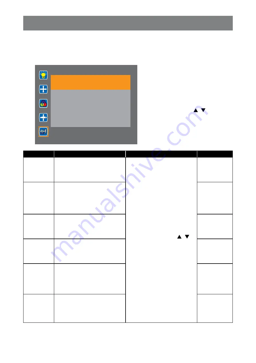
5.5 Setup

Configure the setup settings.

Setup

[email protected]

Ambient 38
Thermal 34

Language

Input

Display Size

Reset

Power Saving

Monitor ID

OSD

1

  Press the 

MENU

 button on the control 

panel or the remote control to call out 

the OSD window.

2

  Select 

Setup

, then press the 

MENU


button on the control panel or the 

ENTER

 button on the remote control.

3

  Press the 

PLUS 

MINUS

 button on the 

control panel or the 

 / 

 button on the 

remote control to select an option.

4

  Press the 

MENU

 button on the control 

panel or the 

ENTER

 button on the 

remote control to enter the adjustment 

mode.

Item

Function

Operation

Range

Language

Chooses the OSD menu language.

Press the 

PLUS

 / 

MINUS

 button 

on the control panel or the 

 / 


button on the remote control to 

select the setting.

English

简体中文

Input

Switches the input source when 

multiple sources are connected.

D-SUB

DVI

HDMI

DP

Display Size

Selects the aspect ratio of the 

screen image

Full Screen

Auto

4:3

Reset

Resets the display to its factory 

default settings.

No

Yes

Power Saving

Enables or disables power saving 

mode. When the LCD display turns 

into power saving mode, the screen 

turns black and the LED indicator 

lights AMBER.

Off

On

Monitor Id

Sets a unique up to 3-digit number 

for the display.

1 to 100

Содержание PO-55F

Страница 1: ...PO 55F PO 55H LED Backlit Display User Manual displays agneovo com ...

Страница 2: ...e Display 10 1 3 1 Unpacking the Display 10 1 3 2 Carrying the Display 11 1 3 3 Setting Down the Display 11 1 3 4 Placing the Display 11 1 4 Wall Mounting Installation 12 1 4 1 VESA Grid 12 1 4 2 Ventilation Requirements for Enclosure Locating 13 1 5 Mounting in Portrait Position 13 1 6 LCD Display Overview 14 1 6 1 Control Panel 14 1 6 2 Input Output Terminals 16 1 7 Remote Control 18 1 7 1 Gener...

Страница 3: ...e Volume 26 3 4 Setting Up the IR Sensor 27 CHAPTER 4 ON SCREEN DISPLAY MENU 28 4 1 Using the OSD Menu 28 4 2 OSD Menu Tree 29 CHAPTER 5 ADJ USTING THE LCD DISPLAY 30 5 1 Luminance 30 5 2 Picture 31 5 3 Color 32 5 4 OSD Settings 33 5 5 Setup 34 CHAPTER 6 APPENDIX 35 6 1 Warning Messages 35 6 2 Supported Resolution 35 6 3 Cleaning 37 6 4 Troubleshooting 38 6 5 Transporting the LCD Display 39 CHAPTE...

Страница 4: ...cation Notice The equipment should draw power from a socket with an attached protection circuit a three prong socket All equipment that works together computer display printer and so on should have the same power supply source The phasing conductor of the room s electrical installation should have a reserve short circuit protection device in the form of a fuse with a nominal value no larger than 1...

Страница 5: ...s We confirm that if its products are handled properly for their intended use they are safe to use according to scientific evidence available today We play an active role in the development of international EMF and safety standards enabling us to anticipate further developments in standardization for early integration in its products Information for U K only WARNING THIS APPLIANCE MUST BE EARTHED ...

Страница 6: ... in accordance with the following code BLUE NEUTRAL N BROWN LIVE L GREEN YELLOW EARTH E The GREEN YELLOW wire must be connected to the terminal in the plug which is marked with the letter E or by the Earth symbol or coloured GREEN or GREEN YELLOW The BLUE wire must be connected to the terminal which is marked with the letter N or coloured BLACK The BROWN wire must be connected to the terminal whic...

Страница 7: ...customers in Canada and U S A This product may contain lead and or mercury Dispose of in accordance to local state and federal regulations For additional information on recycling contact www eia org Consumer Education Initiative Waste Electrical and Electronie Equipment WEEE Attention users in European Union private households This marking on the product or on its packaging illustrates that under ...

Страница 8: ...ction point for the recycling of waste electrical and electronic equipment The separate collection and recycling of your waste equipment at the time of disposal will help to conserve natural resources and ensure that it is recycled in a manner that protects human health and the environment Batteries For EU The crossed out wheeled bin implies that used batteries should not be put to the general hou...

Страница 9: ...tect your rights as a consumer do not remove any stickers from the LCD display Doing so may affect the determination of the warranty period Cautions When Setting Up Do not place the LCD display near heat sources such as a heater exhaust vent or in direct sunlight Do not cover or block the ventilation holes in the housing Place the LCD display on a stable area Do not place the LCD display where it ...

Страница 10: ... wet hands When turning off the display by detaching the power cord wait 6 seconds before re attaching the power cord for normal operation Do not knock or drop the display during operation or transportation Cleaning and Maintenance To protect your display from possible damage do not put excessive pressure on the LCD panel When moving your display grasp the frame to lift do not lift the display by ...

Страница 11: ... for extended periods of time It can be several hours or several days Use a screen saver and run it for extended periods of time Use a black and white image and run it for extended periods of time There are millions of micro transistors inside the LCD display It is normal for a few transistors to be damaged and to produce spots This is acceptable and is not considered a failure IMPORTANT Always ac...

Страница 12: ...ZOOM 7 9 BACKMUSIC 0 VOL Remote control PO 55F PO 55H displays agneovo com PO 55F PO 55H_Quick Guide_V010 Quick Start Guide PO 55F PO 55H LED Backlit Display Quick Start Guide LCD Display Note Remote control is shipped with the supplied AAA batteries For all other regions apply a power cord that conforms to the AC voltage of the power socket and has been approved by and complies with the safety re...

Страница 13: ...y be experienced 1 3 Moving the Display 1 3 1 Unpacking the Display Before unpacking the display prepare a at and stable surface near a wall outlet Set the product box in an upright position according to the arrow markings on the outside of the product box 1 Detach the four locks 2 Open the product box from the top of the box 3 Take the accessories out and remove the top cushion 4 Hold the display...

Страница 14: ...stable surface covered by a protective sheet and a table cushion as shown in the illustration provided 1 3 4 Placing the Display When placing the display keep the display upright Never tilt the display towards the left right or balanced on a single corner of the frame Caution Avoid applying force or using sharp objects on the LCD panel at all times Caution Never press or place anything on the back...

Страница 15: ...length 10 mm longer than the thickness of the mounting bracket and tighten them securely Unit weight 29 2 kg 64 2 lbs PO 55F or 36 7 kg 80 7 lbs PO 55H The equipment and its associated mounting means still remain secure during the test For use only with UL Listed Wall Mount Bracket with minimum weight load 38 0 kg 83 8 lb PO 55F or 47 0 kg 103 6 lb PO 55H 1 4 Wall Mounting Installation To mount th...

Страница 16: ...er be sure to consult the bracket manufacturer for installation location 1 4 2 Ventilation Requirements for Enclosure Locating To allow heat to disperse leave space between surrounding objects as shown in the diagram below 40 mm 40 mm 40 mm 40 mm 1 5 Mounting in Portrait Position This display can be installed in portrait position Rotate 90 degrees counter clockwise such that one of the arrows on t...

Страница 17: ...14 PRODUCT DESCRIPTION 1 6 LCD Display Overview 1 6 1 Control Panel AUTO PLUS MINUS MENU POWER 1 2 4 5 6 7 8 3 PO 55F AUTO PLUS MINUS MENU POWER 1 4 5 6 7 8 2 3 PO 55H ...

Страница 18: ...WER Turns the power on off Note POWER button does not function if the Main Power switch is off 5 MENU Displays the On Screen Display OSD menu Selects items or accepts the settings made in the OSD menu 6 MINUS Decreases the audio output level while OSD menu is off Navigates through the OSD menu items Decreases the adjustment while OSD menu is on 7 PLUS Increases the audio output level while OSD men...

Страница 19: ...16 PRODUCT DESCRIPTION 1 6 2 Input Output Terminals RS232 USB AUDIO OUT AUDIO IN D SUB HDMI DVI DP 1 2 4 5 6 7 9 8 3 10 PO 55F RS232 USB AUDIO OUT AUDIO IN D SUB HDMI DVI DP 1 2 4 5 6 7 9 8 3 10 PO 55H ...

Страница 20: ...licable audio devices Note Headphones and earphones are not supported 6 Audio in Connects with the audio out connector of a video source such as a computer video player when the display is connected to the source via the VGA or DVI connector 7 D SUB Connects with the analog video output VGA of a computer 8 HDMI Connects with devices supporting audio video data using the HDMI interface 9 DVI Connec...

Страница 21: ...ator is not lit then the controls will not function 2 MENU Displays the OSD menu Please refer to page 28 3 NAVIGATION buttons Navigates through menus selects items and adjusts values 4 EXIT Exits the current menu 5 ENTER Selects items or accepts the settings made in the OSD menu 6 SOURCE Switches the video input source Use the buttons to select D SUB DVI HDMI or DP and press the ENTER button to co...

Страница 22: ...te control toward the display s IR sensor within a distance of less than 3 m 9 84 ft and a horizontal and vertical angle of less than 30 degrees when operating the remote control 30 30 Caution The incorrect use of batteries can result in leaks or bursting Be sure to follow these instructions Place AAA batteries matching the and signs on each battery to the and signs of the battery compartment Do n...

Страница 23: ... or personal injury When unplugging the power cord hold the power cord by the plug head Never pull by the cord Loose connections may cause noise Do not plug and unplug the power cord repeatedly in a short period of time When disconnecting the AC power cord be sure to first disconnect the plug from the outlet socket CHAPTER 2 MAKING CONNECTIONS Note The supplied power cord varies depending on the c...

Страница 24: ... audio cable to the AUDIO IN connector of the LCD display and the other end of an audio cable to the AUDIO OUT connector of the computer 3 Press the SOURCE button on the remote control to select the video input source D SUB Once selected the audio input setting will automatically switch to the correct audio source for the video connection 2 2 2 Using HDMI Input Connect one end of an HDMI cable to ...

Страница 25: ...he LCD display and the other end of a DVI cable to the DVI OUT connector of the computer 2 For audio input connect one end of an audio cable to the AUDIO IN connector of the LCD display and the other end of an audio cable to the AUDIO OUT connector of the computer 3 Press the SOURCE button on the remote control to select the video input source DVI Once selected the audio input setting will automat...

Страница 26: ...or of the computer 2 Press the SOURCE button on the remote control to select the video input source DP DP Computer DP 2 3 Connecting External Equipment Video Player 2 3 1 Using HDMI Video Input Connect one end of an HDMI cable to the HDMI connector of the LCD display and the other end of an HDMI cable to the HDMI OUT connector of the video player HDMI HDMI HDMI OUT Video Player DisplayPort ...

Страница 27: ...e LCD display and the other end of an audio cable to the AUDIO IN connector of the audio device 2 3 2 Using DP Video Input Connect one end of a DisplayPort cable to the DP connector of the LCD display and the other end of a DisplayPort cable to the DisplayPort connector of the video player DP DP DisplayPort Video Player AUDIO OUT AUDIO OUT Audio Device AUDIO IN ...

Страница 28: ...URCE button a menu with available input sources will be displayed on the screen Input D SUB DVI HDMI DP If the selected input source signal is not connected to the LCD display or is turned off the no input message is displayed on the screen ATTENTION NO VIDEO INPUT 1 Press the SOURCE button 2 Press the or button to choose the input source then press the ENTER button CHAPTER 3 USING THE LCD DISPLAY...

Страница 29: ...e After pressing the or button the volume adjustment bar is displayed on the screen automatically VOLUME 34 Press the MUTE button to mute the audio POWER F1 F2 F3 F4 MUSIC 2 MOVIE 3 PHOTO 1 ROTATE 5 16 9 4 3 4 ENTER MENU MUTE SLIDE SHOW SOURCE EXIT 6 OSD 8 ZOOM 7 9 BACKMUSIC 0 VOL VOLUME buttons ...

Страница 30: ...sen the IR sensor 2 Unthread the cables from the cable clip 3 Attach the IR sensor to the desired position on the display using the magnets located on the sensor 4 Point the remote control toward the display s IR sensor within a distance of less than 3 m 9 84 ft and a horizontal and vertical angle of less than 30 degrees when operating the remote control Reverse steps 1 3 to return the sensor to i...

Страница 31: ... the submenu 3 Adjust the settings For example Luminance 720x480 59 9Hz Ambient 38 Thermal 34 Brightness 96 OSD 1 Press the PLUS or MINUS button to select the submenu item 2 Press the MENU button to enter the adjustment mode 3 Press the PLUS or MINUS button to adjust the settings 1 Press the or button to select the submenu item 2 Press the ENTER button to enter the adjustment mode 3 Press the or b...

Страница 32: ...ain Menu Submenu Remarks 1 Luminance Brightness Contrast Anti Burn in Auto Dimming See page 30 2 Picture Phase Clock H Position V Position See page 31 3 Color Color Temperature Red Green Blue See page 32 4 OSD Settings Horizontal Vertical OSD Time Out OSD Rotation See page 33 5 Setup Language Input Display Size Reset Power Saving Monitor ID See page 34 Note Availability of some menu items depend o...

Страница 33: ...ect an option 4 Press the MENU button on the control panel or the ENTER button on the remote control to enter the adjustment mode Item Function Operation Range Brightness Adjusts the brightness of the display Press the PLUS MINUS button on the control panel or the button on the remote control to adjust the value 0 to 100 Or i g i n a l S e t t i n g Hi g h S e t t i n g L o w S e t t i n g Contras...

Страница 34: ...34 Phase Clock H Position V Position OSD 1 Press the MENU button on the control panel or the remote control to call out the OSD window 2 Select Picture then press the MENU button on the control panel or the ENTER button on the remote control 3 Press the PLUS MINUS button on the control panel or the button on the remote control to select an option 4 Press the MENU button on the control panel or the...

Страница 35: ... the remote control to enter the adjustment mode Item Function Operation Range Color Temperature Adjusts the color temperature of the display Press the PLUS MINUS button on the control panel or the button on the remote control to select the setting 6500K 9300K 11500K sRGB User Define Red Adjusts the red color Note This item becomes available if you set the Color Temperature to se Define Press the ...

Страница 36: ... panel or the ENTER button on the remote control to confirm the selection Item Function Operation Range Horizontal Moves the position of the OSD menu horizontally Press the PLUS MINUS button on the control panel or the button on the remote control to adjust the value 0 to 100 Vertical Moves the position of the OSD menu vertically 0 to 100 OSD Time Out Changes the OSD menu timer settings where the ...

Страница 37: ...or the ENTER button on the remote control to enter the adjustment mode Item Function Operation Range Language Chooses the OSD menu language Press the PLUS MINUS button on the control panel or the button on the remote control to select the setting English 简体中文 Input Switches the input source when multiple sources are connected D SUB DVI HDMI DP Display Size Selects the aspect ratio of the screen im...

Страница 38: ...perly connected Check if any pin inside the cable connector is twisted or broken 6 2 Supported Resolution VGA Resolution Resolution Refresh Rate Hz Horizontal Frequency KHz Pixel Frequency MHz Standard Type 640x480 60 31 5 25 175 Industrial Standard 75 37 5 31 5 VESA Standard 800x600 60 37 9 40 VESA Guideline 72 48 1 50 VESA Standard 75 46 9 49 5 VESA Standard 1024x768 60 48 4 65 VESA Guideline 70...

Страница 39: ...ity is optimum in HD 1080 mode 1920x1080 60Hz Your PC display screen might appear different depending on the manufacturer and your particular version of Windows Check your PC instruction book for information about connecting your PC to a display When horizontal synchronous signals seem irregular in RGB mode check PC power saving mode or cable connections The display settings table complies to the ...

Страница 40: ...If the surface becomes dirty soak a soft lint free cloth in a mild detergent solution Wring the cloth to remove excess liquid Wipe the surface of the display to remove dirt Then use a dry cloth of the same type to dry Do not scratch or hit the surface of the panel with fingers or hard objects of any kind Do not use volatile substances such as insert sprays solvents and thinners Cabinet Cleaning In...

Страница 41: ... Can hear sound but no picture Improperly connected source signal cable Make sure that both video inputs and sound inputs are correctly connected Can see picture but no sound is heard Improperly connected source signal cable Volume is turned all the way down MUTE function is turned on No external speaker connected Make sure that both video and sound inputs are correctly connected Press the or butt...

Страница 42: ... the LCD monitor inside the supplied protective bag a 2 Place the LCD display down in the lower box b 3 Place the upper box c on the LCD display 4 Place the foam cushion d on top of the LCD display 5 Put all the accessories in the box if necessary 6 Secure the upper box to the lower box with the supplied locks e Then close and tape the upper box a e b c d ...

Страница 43: ... 3 5 mm x 1 Stereo Audio Jack 3 5 mm x 1 Audio Out Stereo Audio Jack 3 5 mm x 1 Stereo Audio Jack 3 5 mm x 1 Internal Speakers 10W x 2 Power Power Supply Internal Internal Power Requirements 100 240Vac 50 60 Hz 100 240Vac 50 60 Hz On Mode 353W On 353W On Stand by Mode 2W 2W Off Mode 1W 1W Operating Conditions Temperature 0 C 40 C 32 F 104 F 0 C 40 C 32 F 104 F Humidity 20 80 non condensing 20 80 n...

Страница 44: ...opening dimension 713 outline dimension 13 3 13 3 400 421 1 421 1 400 565 8 50 4 96 8 564 8 339 3 338 1 50 6 M8xL18 x4 13 3 13 3 117 8 156 5 156 5 7 2 2 PO 55H Dimensions AG Neovo Company Address 5F 1 No 3 1 Park Street Nangang District Taipei 11503 Taiwan Copyright 2020 AG Neovo All rights reserved PO5H00 PO5F00_UM_V011 ...

Отзывы: