background image


– English – 

Mounting and commissioning 

FloCo-Top-2 

33 

6.4 

Pressure test 

When subjecting the suction pipe to a pressure test, the pressure 
connection must not be made at the FloCo-Top-2 unit since the 
check valve integrated in the product does not allow the pressure to 
be applied to the suction line. 


Do not include the check valve in the pressure test. 

6.5 

Pressure loss 

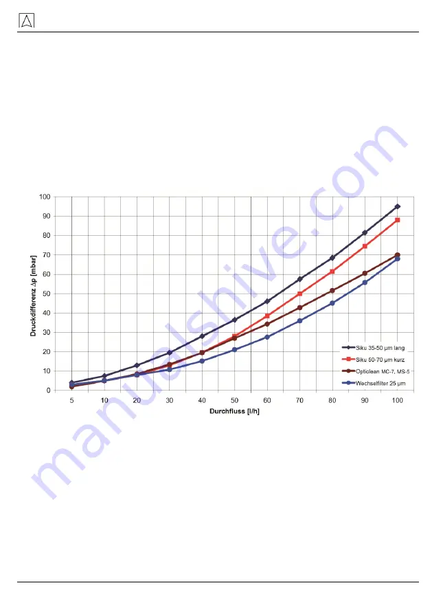
FloCo-Top-2 allows you to use a great variety of filter inserts. See 
the diagram (fig. 13) for the resulting pressure losses.  

Pressure loss with clean filters 


Fig. 32: Pressure loss with various filters 

Содержание FloCo-Top-2 Series

Страница 1: ...hnique pour toute utilisation ultérieure 11 2014 0 854 099 0575 Betriebsanleitung Instruction Manual Notice technique Automatischer Heizölentlüfter mit integriertem Filter Automatic fuel oil de aerator with integrated filter Purgeur d air automatique avec filtre intégré pour fuel FloCo Top 2 2KM Si 2KMF WF 2KM MC 7 2KM MS 5 2MM Si 2KM Optimum MC 18 2KM Optimum Si BRL A Teil 1 EN 12514 2 in Verbind...

Страница 2: ...der Sachschaden folgen 2 Sicherheit 2 1 Bestimmungsgemäße Verwendung Der automatische Heizölentlüfter FloCo Top 2 in Sicherheitsausfüh rung mit integriertem Filter und Absperrventil eignet sich ausschließ lich für den Einsatz in Einstrangsystemen mit Rücklaufzuführung zur kontinuierlichen Entlüftung folgender Flüssigkeiten in Ölfeuerungs anlagen Heizöl EL nach DIN 51603 1 mit 0 20 Fettsäure Methyl...

Страница 3: ...lfunktio nen führen und sind aus Sicherheitsgründen verboten 2 6 Verwendung von Ersatzteilen und Zubehör Durch Verwendung nicht geeigneter Ersatz und Zubehörteile kann das Produkt beschädigt werden Nur Originalersatzteile und Zubehör des Herstellers verwen den 2 7 Haftungshinweise Für Schäden und Folgeschäden die durch Nichtbeachten der tech nischen Vorschriften Anleitungen und Empfehlungen entste...

Страница 4: ...erschuss wird als Rücklauf dem Heizölentlüfter zu geführt und dem Vorlauf beigemischt Bei FloCo Top 2 wird das Öl zur Entlüftung über die Schwimmerkammer zum Umschaltventil ge leitet und kann direkt dem Vorlauf beigemischt werden oder durch Umschalten des Ventils einem erneuten Filtervorgang unterzogen werden Bei einem Opticlean Filtereinsatz werden z B pro Filtergang bei einer mittleren Filterfei...

Страница 5: ... der Brennerverbrauch sondern die Pumpenumlaufmenge wie bei einem Zweistrangfilter durch das Filterelement fließt und vom Tank ankommende Luftbläschen mit dem Volumenstrom weitertransportiert werden Bei Brennern mit einem Verbrauch von weniger als 20 l h empfiehlt sich die Mehrfachfilterung bei größeren Anlagen ist der Heizölent lüfter auf Einfachfilterung einzustellen A Mehrfachfilterung bei Bren...

Страница 6: ...chwimmer Die obere Schwimmerkammer verhindert dass Ölschaum z B bei Inbetriebnahme Filterwechsel durch die Entlüftungsbohrung austreten kann und zeigt Störungen des Entlüf tungsventils an Das Unterdruckmanometer 0 7 bar zeigt die Filterverschmutzung an Ein angestiegener Unterdruck gibt Auskunft über die Filterver schmutzung Das Manometer zeigt zusätzlich einen möglichen sta tischen Vordruck bis ma...

Страница 7: ...terfläche FloCo Top 2KM Optimum Si Wie FloCo Top 2KM Si jedoch mit langer Filtertasse und langem Siku Filter 3 2 Funktion Die Brennerpumpe saugt durch den Filter und über das im Gehäuse eingebaute Rückschlagventil das Heizöl vom Tank an und fördert es zur Düse Die über die Düsenleistung hinausgehende Ölmenge wird von der Pumpe über den Anschlussstutzen der Rücklaufleitung in die Schwimmerkammer ge...

Страница 8: ...G 3 8 a mit 60 Konus für Brenner schlauch Anschluss Tank G 3 8 i am Absperrventil Düsenleistung Max 100 l h Rücklaufstrom Max 120 l h Abscheideleistung Luft Gas abhängig vom Luftgehalt des Brennstoffs 4 l h nur Entlüftungseinheit 6 l h nach EN 12514 3 Einbaulage Schwimmergehäuse senkrecht nach oben Betriebsüberdruck Max 0 7 bar entsprechend stati scher Ölsäule von ca 8 m Saugunterdruck Max 0 5 bar...

Страница 9: ...rt und Lagerung VORSICHT Beschädigung des Produkts durch unsachgemäßen Transport Produkt nicht werfen oder fallen lassen VORSICHT Beschädigung des Produkts durch unsachgemäße Lagerung Produkt gegen Stöße geschützt lagern Produkt nur in trockener und sauberer Arbeitsumgebung lagern Produkte mit sichtbaren Schäden dürfen nicht betrieben werden 6 Montage und Inbetriebnahme Der FloCo Top 2 wird vor de...

Страница 10: ...it des Heizöls m s d Ø 4 nicht empfehlenswert e Empfohlener Bereich nach DIN 4755 2 Bild 11 Nomogramm Beispiel Fördermenge 20 l h Fließgeschwindigkeit Ø 0 23 m s Es wird eine Leitung mit Rohrdurchmesser 8 x 1 mm NW 6 benötigt 6 2 Ermittlung der Saugleitungslänge Bei der Tabelle wird für die Ermittlung der maximal möglichen Saug leitungslänge davon ausgegangen dass der maximale Saugunter druck nich...

Страница 11: ... l h Ø 4 mm 32 26 19 13 7 1 Maximal mögliche Saugleitungslänge m Ø 6 mm 100 100 100 68 36 4 Ø 8 mm 100 100 100 100 100 14 5 kg h 6 l h Ø 4 mm 10 8 6 4 2 1 Ø 6 mm 81 65 49 34 18 2 Ø 8 mm 100 100 100 100 57 7 7 5 kg h 9 l h Ø 4 mm 10 8 6 4 2 0 Ø 6 mm 54 43 33 22 12 1 Ø 8 mm 100 100 100 71 38 4 10 kg h 12 l h Ø 4 mm 8 6 4 3 1 0 Ø 6 mm 40 32 25 17 9 1 Ø 8 mm 100 100 78 53 28 3 Ø 10 mm 100 100 100 100 ...

Страница 12: ...berventil KAV 2 Membran Antiheberventil MAV HKAV Relevante Saughöhe KAV HMAV Relevante Saughöhe MAV Bild 14 Anwendungsbeispiel 3 Düsen leistung Rohr Innen Ø Saughöhe H m 1 5 2 0 2 5 3 0 3 5 4 0 2 5 kg h 3 l h Ø 4 mm 32 26 19 13 7 1 Maximal mögliche Saugleitungs länge m 5 kg h 6 l h Ø 4 mm 10 8 6 4 2 1 7 5 kg h 9 l h Ø 4 mm 10 8 6 4 2 0 Ø 6 mm 54 43 33 22 12 1 10 kg h 12 l h Ø 4 mm 8 6 4 3 1 0 Ø 6 ...

Страница 13: ...hrauben kann der Halter als Schablone verwendet werden 2 Die Saugleitung in das Innengewinde G 3 8 des Gehäuses mit zylindrischer Rohrverschraubung G 3 8 nach DIN 3852 siehe Kapitel 10 Seite 20 oder beiliegender Rohrverschraubung Ø 8 10 mm eindichten Kein Hanf oder Teflonband verwenden 3 Bei weichem oder halbhartem Kupfer Rohr eine Stützhülse verwenden 4 Mit einem Gabelschlüssel SW 22 gegenhalten ...

Страница 14: ...til die Druckübertragung auf die Saugleitung nicht zulässt Das Rückschlagventil nicht in die Druckprüfung einbeziehen 6 5 Druckverlust Der FloCo Top 2 ermöglicht den Einbau verschiedenster Filterein sätze Die dadurch entstehenden Druckverluste können aus dem Diagramm Bild 13 entnommen werden Druckverlust bei Verwendung eines sauberen Filters Bild 15 Druckverlust bei Verwendung verschiedener Filter...

Страница 15: ... durch Mehrfachfilterung Siku Filtereinsatz 50 70 µ Auch bei großen Ölbrennern mit einem Durchsatz von mehr als 20 l h ist die Umstellung auf Mehrfachfilterung möglich Die hier durch bedingte Unterdruckerhöhung kann mit Hilfe des folgenden Diagramms ermittelt werden Bild 16 Druckerhöhung bei verschiedenen Pumpenleistungen ...

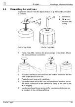
Страница 16: ...ndrehers demontieren Beigelegten Schlauchanschluss montieren 2 Entlüftungsschlauch auf den Schlauchanschluss aufschieben und entlang der Saugleitung zum Tank zurückführen 3 Entlüftungsschlauch mit Kabelbindern fixieren 4 Um einem eventuellen Leitungsverschluss vorzubeugen das andere Ende des Entlüftungsschlauches an der Entlüftungslei tung oder am Rücklaufanschluss der Entnahmearmatur des Tanks an...

Страница 17: ...ist es nicht sinnvoll hier ein FloCo Top 2KM einzusetzen Im Druckbetrieb sollte ein Einstrangfilter mit Rücklauf zuführung eingesetzt werden Wenn anlagenbedingt ein Heizölent lüfter benötigt wird kann ein FloCo Top 2MM mit nachgerüsteter Messing Filtertasse oder Wechselfilterkartusche verwendet werden siehe Kapitel 10 Seite 20 Für diese Anwendung geeignete Vorkehrungen treffen die auch im Störfall...

Страница 18: ... können kann die Filter tasse vor dem Ausbau entleert werden 1 Geeignetes Gefäß mit einem Fassungsvermögen von mindes tens 0 5 Liter unter die Filtertasse stellen 2 Ablassschlauch Ø 6 mm auf die Ablassschraube stecken Das Ende des Ablassschlauchs in das Gefäß hängen 3 Ablassschraube gegen den Uhrzeigersinn drehen 4 Die Überwurfmutter der Filtertasse mit einem Ölfilterschlüssel leicht öffnen Bild 1...

Страница 19: ... Fehlerbehebung Starker Ölschaum in der Schwimmer kammer durch zu viel eingesaugte Luft im Entlüfter mehr als die mögliche Geräteabscheide leistung 4 l h Undichtheit in der Sauglei tung Dichtheitsprüfung der Saug leitung vornehmen Vakuum oder Druckprüfung Undichte Verschraubungen im Saugbereich Verschraubungen abdichten Erstinbetriebnahme ohne separate Ansaugpumpe Ansaugpumpe verwenden Zu groß dim...

Страница 20: ...hädi gungen prüfen Absperrventil an der Entnahmearmatur schließen und Vakuumprü fung min 0 6 bar am Vor laufanschluss des Ölentlüf ters durchführen Brennerpumpe erzeugt kein ausreichendes Vaku um Saugdruckprüfung an der Pumpe durchführen Pumpe muss min einen Unterdruck von 0 4 bar aufbauen Nach einem Filter oder Brennerschlauchwechsel wurde das Entleer oder Bypassventil nach dem Entleervorgang nic...

Страница 21: ...anleitung verbleibt beim Her steller Nachdruck Übersetzung und Vervielfältigung auch aus zugsweise sind ohne schriftliche Genehmigung nicht erlaubt Änderungen von technischen Details gegenüber den Angaben und Abbildungen der Betriebsanleitung sind vorbehalten 13 Kundenzufriedenheit Für uns hat die Zufriedenheit des Kunden oberste Priorität Wenn Sie Fragen Vorschläge oder Schwierigkeiten mit Ihrem ...

Страница 22: ...ell as damage to property 2 Safety 2 1 Intended use The automatic fuel oil de aerator FloCo TOP 2 safety version with integrated filter and shut off valve may only be used in single line systems with return pipe connection for continuous de aeration of the following liquids in oil fired systems Fuel oil EL as per DIN 51603 1 with 0 20 fatty acid methyl ester FAME as per EN 14214 Diesel fuel as per...

Страница 23: ...tions and are prohibited for safety reasons 2 6 Usage of spare parts and accessories Usage of unsuitable spare parts and accessories may cause dam age to the product Use only genuine spare parts and accessories of the manufac turer 2 7 Liability information The manufacturer shall not be liable in any form whatsoever for direct or consequential damage resulting from failure to observe the technical...

Страница 24: ...d directly to the supply or it can be filtered again by switching the valve With an Opticlean filter insert 50 of the particles in the circulated oil are removed with a filter rating of 5 μm per filtration A second fil tration removes another 50 of the remaining particles 5 20 µm so that a total of 75 of all particles are removed After the third filtra tion the rate increases to 87 5 after the fou...

Страница 25: ...ems should be operated with single filtration A Multiple filtration at a burn er consumption of 20 l h B Single filtration at a burner consumption of 20 l h Fig 19 Single or multiple filtration 3 1 Versions Fig 20 FloCo Top 2KM Si part no 70110 Fig 21 FloCo Top 2KMF WF Art Nr 70111 Fig 22 FloCo Top 2KM MC 7 part no 70112 Fig 23 FloCo Top 2MM Si part no 70113 Fig 24 FloCo Top 2KM Optimum MC 18 part...

Страница 26: ...ck the suction capacity It is sufficient to close the shut off valve at the filter to check the suction capacity The check valve has an integrated overpressure device which opens at 1 5 bar it become ineffective if e g flow and return lines are in terchanged The product is equipped with a sintered plastic filter FloCo Top 2KMF WF Like FloCo Top 2KM Si but with a replacea ble filter cartridge Speci...

Страница 27: ...20 30 mm above the bottom the floats begin to operate and actuate the bypass valve thus deliv ering the de aerated return oil to the suction pipe This way the sys tem only withdraws the amount of oil from the tank via the filter which is actually needed for combustion The major part of the volume flow to the tank consists of de aerated fuel oil and a small portion of fuel oil from the tank which m...

Страница 28: ...essure 6 bar Filter insert 50 µm sintered plastic Materials De aerator hood Transparent plastic Filter cup Transparent plastic Housing Zinc die cast Operating temperature range Ambient medium 5 C to 60 C 4 1 Approvals tests and conformities FloCo Top 2 is TÜV tested report no S 133 2013 E2 5 Transport and storage CAUTION Damage to the product due to improper transport Do not throw or drop the prod...

Страница 29: ...Nozzle consumption burner Brenner l h b Inside diameter nominal diameter of the suction line mm c Flow rate of the fuel oil m s d Ø 4 not advisable e Recommended range as per DIN 4755 2 Fig 28 Nomograph Example Volume 20 l h flow rate Ø 0 23 m s A pipe with a pipe diame ter of 8 x 1 mm nominal diameter 6 is required 6 2 Determination of suction line length For the determination of the maximum poss...

Страница 30: ...h Ø 4 mm 32 26 19 13 7 1 Maximum possible suction line length m Ø 6 mm 100 100 100 68 36 4 Ø 8 mm 100 100 100 100 100 14 5 kg h 6 l h Ø 4 mm 10 8 6 4 2 1 Ø 6 mm 81 65 49 34 18 2 Ø 8 mm 100 100 100 100 57 7 7 5 kg h 9 l h Ø 4 mm 10 8 6 4 2 0 Ø 6 mm 54 43 33 22 12 1 Ø 8 mm 100 100 100 71 38 4 10 kg h 12 l h Ø 4 mm 8 6 4 3 1 0 Ø 6 mm 40 32 25 17 9 1 Ø 8 mm 100 100 78 53 28 3 Ø 10 mm 100 100 100 100 6...

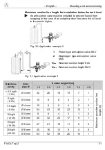
Страница 31: ...AV 2 Diaphragm type anti siphon valve MAV HKAV Relevant suction height KAV HMAV Relevant suction height MAV Fig 31 Application example 3 Nozzle ca pacity Inner pipe Ø Suction height H m 1 5 2 0 2 5 3 0 3 5 4 0 2 5 kg h 3 l h Ø 4 mm 32 26 19 13 7 1 Maximum possible suction line length m 5 kg h 6 l h Ø 4 mm 10 8 6 4 2 1 7 5 kg h 9 l h Ø 4 mm 10 8 6 4 2 0 Ø 6 mm 54 43 33 22 12 1 10 kg h 12 l h Ø 4 mm...

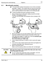
Страница 32: ...crews 2 Mount the suction line into the female thread G 3 8 of the hous ing with a cylindrical screwed pipe connection G 3 8 as per DIN 3852 see chapter 10 page 20 or with the enclosed pipe connection Ø 8 10 mm and seal it Do not use hemp or Teflon tape 3 Use a support bushing in the case of soft or semi soft copper pipes 4 Lock with an open ended spanner size SW 22 and tighten the screwed connect...

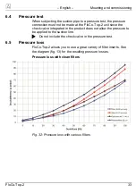
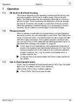
Страница 33: ... unit since the check valve integrated in the product does not allow the pressure to be applied to the suction line Do not include the check valve in the pressure test 6 5 Pressure loss FloCo Top 2 allows you to use a great variety of filter inserts See the diagram fig 13 for the resulting pressure losses Pressure loss with clean filters Fig 32 Pressure loss with various filters ...

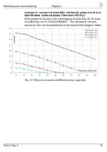
Страница 34: ... tiple filtration sintered plastic filter insert 50 70 µ Even greater oil burners with a throughput of more than 20 l h allow for switching over to multiple filtration The increase in vacuum caused by this can be determined on the basis of the diagram below Fig 33 Pressure increase at different pump capacities ...

Страница 35: ...emove the cover using a screwdriver Mount the enclosed hose connection 2 Push the vent hose onto the hose connection and route it to the tank next to the suction line 3 Fixate the vent hose with cable ties 4 Mount the other end of the vent hose to the de aeration line or the return connection of the withdrawal fitting at the tank to pre vent clogging 5 Use the enclosed hose connector for connectio...

Страница 36: ...s not meaningful to use FloCo Top 2 KM in this mode In pressure mode it is recommended to use a single line filter with return pipe connection If the system requires a oil de aerator you can use a FloCo TOP 2MM with retrofitted brass filter cup or re placeable filter cartridge see chapter 10 page 20 In the case of such applications take appropriate measures to prevent the maximum permissible inlet...

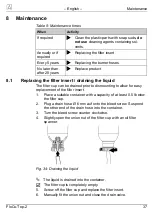
Страница 37: ...rained prior to dismounting to allow for easy replacement of the filter insert 1 Place a suitable container with a capacity of at least 0 5 l below the filter cup 2 Plug a drain hose Ø 6 mm auf onto the bleed screw Suspend the other end of the drain hose into the container 3 Turn the bleed screw counter clockwise 4 Slightly open the union nut of the filter cup with an oil filter spanner Fig 34 Dra...

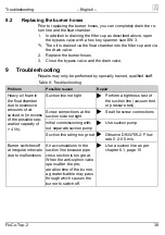
Страница 38: ...r Heavy oil foam in the float chamber due to excessive amounts of air sucked in in excess of the possible sep aration capacity of 4 l h Suction line not tight Perform a tightness test of the suction line vacuum test or pressure test Screw connections at the suction side not tight Seal the screw connections Initial commissioning with out separate suction pump Use suction pump Suction line rating to...

Страница 39: ...lose the stop valve at the withdrawal fitting and per form a vacuum test at least 0 6 bar at the supply con nection of the oil vent Burner pump does not generate a sufficient vacu um Perform a suction test at the pump The pump must gen erate a vacuum of at least 0 4 bar After a filter or burner hose replacement the drain valve or the bypass valve have not been closed after draining Close valves Ot...

Страница 40: ...tions These operating instructions may not be reprinted translated copied in part or in whole without prior written consent We reserve the right to technical modifications with reference to the specifications and illustrations in this manual 13 Customer satisfaction Customer satisfaction is our prime objective Please get in touch with us if you have any questions suggestions or problems concerning...

Страница 41: ...er le risque Terme d aver tissement Signification ATTENTION ATTENTION signale une situation potentiellement dangereuse qui en cas de non respect peut en traîner des blessures moyennes ou légères ou des dommages matériels 2 Sécurité 2 1 Utilisation conforme Le purgeur d air automatique pour fuel FloCo Top 2 version de sé curité avec filtre intégré et robinet d arrêt est destiné exclusivement à l ut...

Страница 42: ...s que par de personnel spé cialisé et qualifié 2 5 Modification du produit Toute modification du produit risque de générer des dysfonctionne ments et est par conséquent interdite pour des raisons de sécurité 2 6 Utilisation de pièces détachées et accessoires L utilisation d accessoires ou pièces détachées non conformes peut endommager le produit N utilisez que des accessoires et pièces détachées d...

Страница 43: ...air automatique pour fuel et mé langé avec le flux d aspiration Avec FloCo Top 2 le fuel est dirigé vers la chambre de flotteur via la vanne de commande et peut ainsi revenir dans le circuit aller ou selon la position de la vanne il peut repasser au travers du filtre Avec l élément filtrant Opticlean et un pouvoir de filtration de 5 μm 50 des particules sont retenues à chaque passage Au deuxième t...

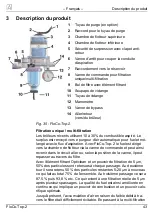
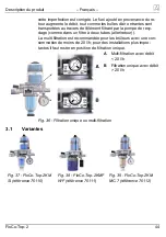
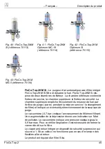
Страница 44: ...tre à deux tubes aller retour La multi filtration est recommandée pour les brûleurs avec une con sommation de moins de 20 l h pour des installations plus impor tantes il faut rester en position de filtration unique A Multi filtration avec débit 20 l h B Filtration unique avec débit 20 l h Fig 36 Filtration unique ou multi filtration 3 1 Variantes Fig 37 FloCo Top 2KM Si référence 70110 Fig 38 FloC...

Страница 45: ...mbre supérieure empêche l écoulement du mousse de fuel par l orifice de purge par ex pendant la mise en service le changement de filtre et indique un éventuel dysfonctionnement de la soupape de purge Le vacuomètre 0 7 bar indique l encrassement de l élément filtrant Une augmentation de la dépression donne une indication sur l état de pollution Le vacuomètre indique une pression statique jusqu à 0 ...

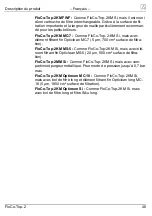
Страница 46: ...lean MC 7 5 µm 700 cm surface de filtra tion FloCo Top 2KM MS 5 Comme FloCo Top 2KM Si mais avec élé ment filtrant fin Opticlean MS 5 20 µm 500 cm surface de filtra tion FloCo Top 2MM Si Comme FloCo Top 2KM Si mais avec com partiment purgeur métallique Pour mode de pression jusqu à 0 7 bar max FloCo Top 2KM Optimum MC 18 Comme FloCo Top 2KM Si mais avec bol de filtre long et élément filtrant fin O...

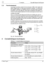
Страница 47: ...fuel purgé d être recyclé au tube d aspiration Ce qui fait que seule la quantité de fuel utile au brûleur est aspirée dans le ré servoir au travers du filtre Le débit volumique vers la pompe est ainsi principalement constitué de fuel purgé et secondairement de fuel en provenance du réservoir qui peut encore contenir de l air 1 QRéservoir QGi cleur 2 QRetour 3 QAller 4 QDicleur Fig 44 Fonctionnemen...

Страница 48: ... Matériaux Compartiment purgeur Plastique transparent Bol du filtre Plastique transparent Boîtier Zinc moulé sous pression Plage de température Ambiante fluide 5 C à 60 C 4 1 Certifications homologation conformités FloCo Top 2 est testé par le TÜV rapport n S 133 2013 E2 5 Transport et stockage ATTENTION Endommagements dus à un transport non conforme Ne pas lancer ou laisser tomber le produit ATTE...

Страница 49: ...ent de 0 2 0 5 m s et effectuer les vérifications a Consommation du gicleur du brûleur l h b Diamètre intérieur DI de la conduite d aspiration mm c Vitesse d écoulement du fuel m s d Ø 4 non recommandé e Plage recommandée selon DIN 4755 2 Fig 45 Nomogramme Exemple Refoulement 20 l h vitesse d écoulement Ø 0 23 m s Il faut prévoir une conduite de 8 x 1 mm diamètre intérieur DI 6 6 2 Déterminer la l...

Страница 50: ... 5 2 0 2 5 3 0 3 5 4 0 2 5 kg h 3 l h Ø 4 mm 32 26 19 13 7 1 Longueur max admissible de la conduite d aspiration m Ø 6 mm 100 100 100 68 36 4 Ø 8 mm 100 100 100 100 100 14 5 kg h 6 l h Ø 4 mm 10 8 6 4 2 1 Ø 6 mm 81 65 49 34 18 2 Ø 8 mm 100 100 100 100 57 7 7 5 kg h 9 l h Ø 4 mm 10 8 6 4 2 0 Ø 6 mm 54 43 33 22 12 1 Ø 8 mm 100 100 100 71 38 4 10 kg h 12 l h Ø 4 mm 8 6 4 3 1 0 Ø 6 mm 40 32 25 17 9 1 ...

Страница 51: ...on KAV 2 Valve anti siphon à membrane MAV HKAV Hauteur relevant d aspiration KAV HMAV Hauteur relevant d aspiration MAV Fig 48 Exemple d application 3 Débit du gicleur Ø inté rieure de tube Hauteur d aspiration H m 1 5 2 0 2 5 3 0 3 5 4 0 2 5 kg h 3 l h Ø 4 mm 32 26 19 13 7 1 Longueur max admissible de la conduite d aspiration m 5 kg h 6 l h Ø 4 mm 10 8 6 4 2 1 7 5 kg h 9 l h Ø 4 mm 10 8 6 4 2 0 Ø...

Страница 52: ... tôle Pour visser les vis à tôle il est possible de se servir du support comme gabarit 2 Utiliser un raccord cylindrique G 3 8 selon DIN 3852 voir cha pitre 10 page 20 ou le raccord fourni pour tube Ø 8 10 mm afin de raccorder la tube d aspiration au taraudage G 3 8 du boî tier En aucun cas employer du ruban téflon ou du chanvre 3 Avec du tube cuivre mi dur ou recuit utiliser un fourreau de ren fo...

Страница 53: ...poré à l appareil ne permet pas d appliquer la pression à la conduite d aspiration Le clapet anti retour ne doit de ce fait pas être inclus à l essai de pression 6 5 Perte de pression FloCo Top 2 permet l utilisation de différents types d élément fil trants La perte de charge engendrée est indiquée dans le dia gramme figure 13 Pertes de charge avec un filtre propre Fig 49 Pertes de charge selon le...

Страница 54: ...leur causée par multi filtration élément filtrant Siku 50 70 µ Même avec des brûleurs importants ayant un débit de plus de 20 l h il est possible de sélectionner la position multi filtration L augmen tation de la dépression résultante peut être déterminée à l aide du diagramme suivant Fig 50 Augmentation de la dépression selon puissance de pompe ...

Страница 55: ...o Top 2KM à l aide d un tourne vis Monter le raccord tuyau fourni 2 Pousser le tuyau de purge sur le raccord de tuyau et le poser le long de la ligne d aspiration vers le réservoir 3 Fixer le tuyau de purge à l aide de colliers 4 Raccorder l autre extrémité du tuyau à la conduite d aspiration ou au raccord de retour de l unité de prélèvement pour empê cher une obturation possible de la conduite 5 ...

Страница 56: ...acuer provenant de l aspiration Dans ce cas un filtre monotube avec retour est préfé rable Si l installation nécessite toutefois un purgeur d air pour fuel on pourra utiliser un FloCo Top 2MM avec un bol de filtre en laiton ou avec une cartouche de filtre interchangeable voir chapitre 10 page 20 Pour cette application prenez des précautions appropriées pressostat soupape de décharge etc en cas d i...

Страница 57: ...il est possible de vider le bol de filtre au préalable 1 Positionner un récipient d une capacité d au moins 0 5 litres sous le bol de filtre 2 Pousser un tuyau de vidange Ø 6 mm sur le bouchon de vi dange Positionner l extrémité du tuyau de vidange dans le réci pient 3 Tourner le bouchon de vidange dans le sens antihoraire 4 Desserrer légèrement l écrou raccord du bol de filtre avec une clef pour ...

Страница 58: ...ause possible Action corrective Mousse dans la chambre de flotteur causé par une vo lume excessive d air aspiré supérieur à la capacité de purge 4 l h Fuite dans la conduite d aspiration Effectuer un essai d étan chéité de la conduite d aspi ration pression ou dépres sion Raccords non étanches sur l aspiration S assurer de l étanchéité des raccords Première mise en service sans pompe d aspiration ...

Страница 59: ...min 0 6 bar La pompe du brûleur ne crée pas une dépression suffisante Effectuer un essai d aspira tion de la pompe La pompe doit générer une dépression de 0 4 bar au moins Lors d un remplacement de filtre ou de tuyau du brûleur la vanne de vidange ou la vanne de bypass n a pas été refermée Fermer les vannes Autre dérangement Envoyer le produit au fabri cant 10 Mise hors service et élimination 1 Dé...

Страница 60: ...techniques relatives aux infor mations et illustrations présentes dans cette notice technique 13 Satisfaction client La satisfaction du client est notre première priorité Nous vous re mercions de nous faire part de toutes vos questions et suggestions et de nous communiquer les difficultés que vous pourriez rencontrer lors de l utilisation de nos produits 14 Adresses Les adresses de nos filiales da...

Страница 61: ...e de vidange long 20257 20262 Filtertasse Messing Druckbetrieb Filter cup brass pressure mode Bol de filtre laiton mode pression 20261 O Ring für Filtertasse O ring for filter cup Anneau torique pour bol de filtre 20422 Ersatz Wechselfilterkartusche Spare replaceable filter cartridge Cartouche de filtre interchangeable 70010 Wechselfilter Adapter Replaceable filter adapter Adaptateur filtre interc...

Страница 62: ... vacuum gauge Connection thread G1 8 Range 0 7 0 9 bar Manomètre de dépression rechange Filetage G1 8 Plage d affichage 0 7 0 9 bar 70030 Rohrverschraubung nach DIN 3852 mit Kupfer Flachdichtung Screwed pipe con nection as per DIN 3852 with flat copper gasket Raccord tube selon DIN 3852 avec gar niture plate en cuivre Rohr Pipe Tube Ø 6 mm Rohr Pipe Tube Ø 8 mm Rohr Pipe Tube Ø 10 mm Rohr Pipe Tub...

Страница 63: ...e MAV Valve anti siphon à membrane MAV 20139 Entlüftungsschlauch PA 4 x 1 mm 50 m Rolle Vent hose PA 4 x 1 mm 50 m reel Tuyau de purge PA 4 x 1 mm rouleau de 50 m 820 030 0410 Opticlean Feinstfilter 5 20 µm kurz Opticlean ultra fine filter 5 20 µm short Opticlean filtre ultra fin 5 20 µm court MC 7 20319 Opticlean Feinstfilter 5 20 µm lang Opticlean ultra fine filter 5 20 µm long Opticlean filtre ...

Страница 64: ...70 µm blue Court 50 70 µm bleu Lang 50 70 µm blau Long 50 70 µm blue Long 50 70 µm bleu 20038 20053 Sikusieb Sintered plastic sieve Tamis Siku Kurz 35 µm weiß Short 35 µm white Court 35 µm blanc Lang 35 µm weiß Long 35 µm white Long 35 µm blanc 20035 20049 Filzsieb Felt sieve Tamis feutre 25 Stück pieces pièces 100 Stück pieces pièces 20031 20034 ...

Отзывы: