background image

Installation

05

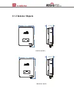
3.1.2 Exterior Objects

HNS7000-8000TL

370mm

510mm

HNS9000-10000TL

188mm

167mm

370mm

527mm

Содержание HNS10000TL

Страница 1: ...Installation and Operation Manual On Grid PV Inverter Version 03 610100007100 Building 7 No 333 Wanfang Rd Minhang District Shanghai China 201112 ...

Страница 2: ...l Connection 4 1 PV Connection 4 2 Grid Connection 4 3 Earth Connection 4 4 Communication Connection 5 Operation 5 1 Control Panel 5 2 Menu Structure 5 3 Setting 5 3 1 Startup 5 3 2 Voltage Range 5 3 3 Frequency Range 6 Commissioning 7 Start up Shut Down 7 1 Start up 7 2 Shut down 7 3 Restart 8 Maintenance Trouble Shooting 8 1 Maintenance 8 2 Trouble Shooting 9 Specifications Contents 22 22 22 23 ...

Страница 3: ...ualified personnel Single Phase Two MPPT Tracker HNS7000TL HNS8000TL HNS9000TL HNS10000TL Please keep this manual stored carefully and accessible at any time About This Manual 01 The typical connection diagram for the entire PV system is on grid PE WIFI RS485 Cloud server Web APP PV Inverter Circuit Breaker N L AC Grid Surge Protective Device CircuitBreaker SurgeProtective Device DCA1 DCA1 PVA PV ...

Страница 4: ...operation To reduce the risk of injury do not touch the cover heat sink at the back of the PV Inverter or nearby surfaces while Inverter is operating Safety Symbols 02 Type Single Phase Two MPPT Trackers HNS7000TL HNS8000TL 33 6 38 3 63A 63A HNS9000TL HNS10000TL 45 50 100A 100A Max AC Current A Rated current of AC breaker A Circuit Breaker and Surge Protector Recommendation Note The Inverter can b...

Страница 5: ... installation operation and maintenance Safety Symbols 03 2 2 Explanations of Symbols Danger of electric shock The inverter contains fatal DC and AC power All work on the inverter must be carried out by qualified personnel only Beware of hot surface The inverter s housing may reach uncomfortably hot 60 C 140 F under high power operation Do not touch the inverter enclosure when operation Residual p...

Страница 6: ...tional DC Connector sets Monitor Module Grounding Terminal 1 2 3 4 5 6 7 8 1 1 1 1 1 1 1 4 Solar Inverter Certificate Of Inspection Quick Installation Instructions Warranty Card Monitoring Quick Installation Instructions Wall Mounting Bracket Waterproof Cover Wiring Cover Screw Note DC connectors NO 7 8kW 3 pairs 9 10kW 4 pairs Unpacking On receiving the inverter please check to make sure the pack...

Страница 7: ...Installation 05 3 1 2 Exterior Objects HNS7000 8000TL 370mm 510mm HNS9000 10000TL 188mm 167mm 370mm 527mm ...

Страница 8: ...stallation 06 Inverter Terminals HNS9000 10000TL HNS7000 8000TL 3 6 1 2 4 5 No 1 2 3 4 5 6 DC Switch DC Connectors For PV Strings DC Connectors For PV Strings AC Connector Zero Injection Optional Monitor Module Items ...

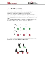
Страница 9: ... or corrosion materials where is suitable for inverter s weight and dimensions The ambient temperature should be within 25 60 between 13 F and 140 F The installation of inverter should be protected under shelter Do not expose the inverter to direct sunlight water rain snow spray lightning etc Installation 07 3 1 3 Mounting Location The inverter should be installed vertically on the wall or lean ba...

Страница 10: ...Installation 08 3 2 Mounting Keep enough space for sufficient heat dissipation convenient operation and maintenance Step 1 Step 2 300mm 300mm 50m m 300mm 500mm 264mm 219mm 17mm ...

Страница 11: ...ollowed The open circuit voltage and short circuit current of PV string should not exceed the reasonable range of the inverters The isolation resistance between PV string and ground must exceed 10 kΩ The polarity of PV strings are correct Use the DC plugs in the accessory The lightning protector should be equipped between PV string and inverter Disconnect all of the PV DC switch during wiring 4 1 ...

Страница 12: ...nnection 10 Step 1 Step 2 Step 3 MC MC Note PV cable sugges on Cross sec on 4mm Note A click will be heard when the connectors are assembled correctly Note The cable should be ghtly connected by the crimping pliers ...

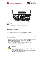
Страница 13: ... from AC distribution box are correctly connected Use the AC plugs in the accessory The surge protector should be equipped between grid and inverter Disconnect the AC grid switch during wiring Electrical Connection 11 4 2 Grid Connection Warning The fatal high voltage may on the AC side please comply with electric safety when connecting Please make sure the right line of AC grid connected with inv...

Страница 14: ... the stripped wire harness to the terminal wrap the joint position with insulation tape Electrical Connection 12 Step 2 Step 1 Note Unscrew the row of screws insert the wire harness into the U W PE caps one by one and tighten the screws U ACL Live line W ACN Neutral line 10 0 5mm The wiring terminals should be wrapped with insula on tape otherwise it will cause a short circuit and damage the inver...

Страница 15: ...Electrical Connection 13 Step 3 Fix the junction box with the wiring cover screws in the accessories and tighten the waterproof connector 4x ...

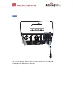
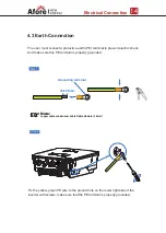
Страница 16: ...this PE terminal is properly grounded Step 1 Step 2 Note copper cable or aluminum cable Cable diameter 6mm Note copper cable or aluminum cable Cable diameter 6mm Grounding terminal 10 0 5mm Fix the yellow green PE wire to the ground hole on the lower right side of the inverter with screws make sure that the PE terminal is properly grounded ...

Страница 17: ... the data on the PC tablet and smart phone WIFI Ethernet GPRS RS485 communication is applicable to the inverter Please refer to Communication Configuration Instruction for detailed instruction Install the WIFI Ethernet GPRS RS485 Communication 4 4 Communication Connection Step 1 Step 2 Wifi GPRS Ethemet ...

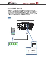
Страница 18: ...rid inverters Its main function is to measure the forward and reverse power on the grid connected side and transmit data to the inverter through RS485 communication to ensure that the power of the inverter is less than or equal to the user s home load and no current flows into the grid 1 6 7 8 PIN Assignment RS485 A 24 RS485 B 25 Zero Injection Port pin assignment 12345678 RJ45 Plug ...

Страница 19: ...in parallel with Smart Meter make sure the total load power not exceed Smart Mater s limitation Grid Load WiFi Ethernet GPRS Router Cloud Server Weather Sta on Afore Smart Meter PV Inverter PV Array Energy Meter PV Inverter PV Array PV Inverter PV Array Afore Smart Meter ...

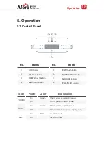
Страница 20: ...ton 5 6 8 7 FAULT LED Indicator POWER LED Indicator ENT Touch Button GRID LED Indicator Sign Color Explanation POWER Green On Off On Off On Off Green Red FAULT The inverter can detect DC power No DC power or low DC power The inverter is supplying power The inverter has stopped to supply power inverter the fails inverter no fault GRID Power 2 3 1 4 5 6 7 8 ...

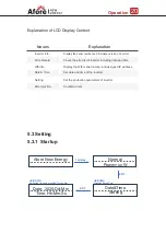
Страница 21: ...nge Volt Range Del Err Record 10min OVR Coefficient Del Arr Record Q Var Mode PassWord xxxx Function Enable Inverter Info First Level Menu Second Level Menu Third Level Menu Wifi Info IP Wifi 192 168 xx xx S N Wifi xxxxxx Error Record No Error Date Time Time Hh Mm Ss Date 2020 Dd Mm Zero Injection PassWord xxxx HNS8000TL Version M Vxxx Version S Vxxx Version C Vxxx S N Machine S6xxxxxxxx ...

Страница 22: ... and time Display the WIFI serial number and assigned IP address Set date and time of the inverter Countercurrent Set the protection parameters of inverter Error Record Wifi Info Date Time Zero Injection Setting Operation 20 UP DOWN Adjust the time and press ENT to confirm UP DOWN Selection Date Time ENT Afore New Energy Normal Power xx W 1s Delay ENT Date Time Setting Date 2020 Dd Mm Time Hh Mm S...

Страница 23: ...XXXV Time xxx 20ms ENT ENT ENT ENT UP DOWN choose Freq Range UP DOWN choose Setting UP DOWN set protection time UP DOWN set protection time press ENT to confirm UP DOWN set level 2 frequency lower limit UP DOWN set protection time UP DOWN choose PassWord xxxx UP DOWN set protection time UP DOWN set level 1 frequency upper limit protection UP DOWN set level 2 frequency upper limit protection UP DOW...

Страница 24: ...en the inverter and the public grid Turn on the DC switch between PV panels and the inverter if any Turn on the DC switch on the inverter Inverter will enter into standby mode and the LCD screen lights up and show contents and then complete the first setting of the inverter according to 5 3 1 The LED will be lighted up after the inverter enter into running states Please check the following require...

Страница 25: ...se according to trouble shooting table find related solutions Turn off the DC switch on the inverter Turn off the DC switch between PV panels and the inverter if any Close the AC switch between the inverter and the public grid 8 Maintenance Trouble Shooting Shut down the inverter according to Chapter 7 2 Start up the inverter according to Chapter 7 1 7 3 Restart 8 1 Maintenance 8 2 Trouble Shootin...

Страница 26: ...uency is back to normal If fault still occurs continuously and frequently please ask help for local distributors Isolation Fault PV Fault The impedance between ground and PV PV is too low beyond the reasonable range Check whether the battery and wiring are immersed in water and whether the insulation layer is damaged and then make corrections If the fault occurs continuously and frequently please ...

Страница 27: ...e Bus High Volt Bus voltage is too high and beyond the protection range Bus Low Fault When inverter is running bus voltage is lower than the normal value beyond the protection range Power off then restart Ref Chapter6 If fault still occurs continuously and frequently please ask help for local distributors Auto Test Fail Automatic test failed No Utility No continuous utility Power off the inverter ...

Страница 28: ...it Power off then restart Ref Chapter6 If fault still occurs continuously and frequently please ask help for local distributors Eeprom Fault Eeprom abnormal System Fault Type of Fault Name Description Recommend Solution Consistent Fault The detection results of the two CPUs for the same voltage and frequency are different Self Lock Inverter is locked at the waiting interface Grid Volt AD Grid volt...

Страница 29: ...ht Power Consump on W Max Opera on Al tude m EMC Standard Safety Standard Grid connec on 3 50 60 Convec on Aluminum 25 60 Transformerless 0 100 4000 40 HNS9000TL 1 IP65 HNS10000TL HNS7000TL 7700 7000 33 6 98 20 97 95 17 19 510 x 370 x 167 527 x 370 x 188 9800 11200 14 26 18 35 2 3 12600 600 70 550 220 550 360 70 MC4 14000 26 26 35 35 2 4 HNS8000TL HNS9000TL HNS10000TL HNS7000TL HNS8000TL HNS9000TL...

Отзывы: