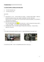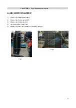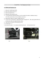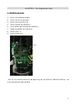
background image


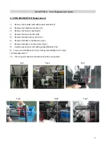
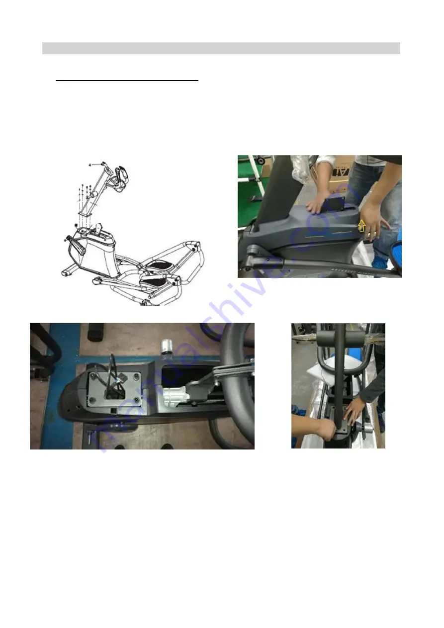
4.5 CONS

1)  Remove

2)  Remove

3)  Loosen 

4)  Pull the

5)    Install n


SOLE MAS

e the console

e the cover o

 the 4 bolts t

e console cab

new console 


    Fig-


CHA

ST REPLA

e and discon

of the consol

to remove th

ble up throug

mast with 4 

-2                   

APTER 4:

ACEMENT

nnect the con

e mast (Fig-

e mast, care

gh the new m

bolts (Fig-3)


  Part Rep

nsole cable. 

1) 

efully pulling t

mast. 


placement 


the console 


Guide      

cables out of


  Fig


f the mast. 

g-1 

    Fig-3 

28


8

Содержание Pro 7.2AI

Страница 1: ...NSO A Kyl ON Issue Rev da Approval le Schweitz e date 20 vision ate zer S 016 11 14 7 Servic Edition Edition ti Review 7 2AI ce Ma n 01 me 01 w anual Doc No Page o SM TM Editor Alex Tang 1 M AF 006 36...

Страница 2: ...Pro oduct B Browse e 2 2...

Страница 3: ...peed Does Not Display 17 3 3 3 Heart Rate Issues 18 3 3 4 Quick Key Issue 19 3 3 5 Noise 20 3 3 6 No Resistance or Incorrect Resistance 21 3 3 7 No Bluetooth Function 22 3 3 8 No Function or Noise on...

Страница 4: ...4 Contents cont 4 9 ECB Motor Replacement 32 4 10 MCB Replacement 33 4 11 Flywheel replacement 34 4 13 Incline motor replacement 35 4 11 Console circuit board replacement 36...

Страница 5: ...1 1 Serial l Number CH Location HAPTER 1 Serial Number Loca ation 5 5...

Страница 6: ...ndicate wha KNOB rotate g start your w st incline in s o adjust resis reach desire d to reach de d off h speakers w MP3 player CK plug your ged into the power tablet or rea T display wh R 2 Con astic...

Страница 7: ...es burne wn as BPM both pulse g ws the curren w many minu Minute urrent user po CHAPTER nds View the dicates distan es how fast t vel of the po ed beats per mi grips nt level of res utes it takes t ow...

Страница 8: ...2 2 Engin neering mo ode instruc CHAPTER ction R 2 Console Instru uction 8 8...

Страница 9: ...CHAPTER R 2 Console Instru uction 9 9...

Страница 10: ...3 1 ELEC 7 2AI SCH CTRICAL D HEMATIC DIAGRAM MCB EC CHAPTER CB R 3 Troubleshooting 10 0...

Страница 11: ...Console c connection n layout CHAPTER R 3 Troubleshooting 11...

Страница 12: ...Assembly c 3 2 1 Boa 1 ECB JP01 C JP02 S JP03 N connection ard Connec Console conn Speed senor NC layout ctor instruc nection r connection CHAPTER ction R 3 Troubleshooting Fig 1 12 2...

Страница 13: ...nication munication pro put board d nector Action Cond er seconds reg M from speed k there is no co with console tocal Fig 2 Table L L L dition gularly The C sensor ount signal fee or not obey the 1 L...

Страница 14: ...8 JP9 JP10 e control boa To Fro NC Fro Fro To To To To To ard LCD display om heart rate om Quick key om Quick key MCB Audio In O Speaker FAN Keypad Blu e grip y Left hand b y right hand b ut interface...

Страница 15: ...at a low battery status c The HR strap is damaged d The HR grips are damaged e The HR cannot display value 3 3 3 4 QUICK KEY ISSUES a No contact between keypad and overlay b Keypad malfunctions c No c...

Страница 16: ...Support 3 Check if the power cord is not pinched or damaged and is properly plugged into the outlet and the machine 4 Remove the console and check if the console cable has good connection Test console...

Страница 17: ...see if the sensor wire JP02 is connected well and not damaged page 12 Fig 1 3 Check to see if one corner of the sensor is aligned with the magnet and the distance less than 5mm 4 Test speed sensor wi...

Страница 18: ...n reestablish contact with the HR grip d With a multi meter set for DC voltage place one terminal on each of the HR grip plates The HR grip should give a voltage reading of between 0 5 and 2 0VDC If t...

Страница 19: ...ON a Remove the back of console and see if the keypad connecting ribbon cable is connected properly to the console control board Reconnect the cable and test the keypad for function Page14 JP4 JP5 b I...

Страница 20: ...the conso hat the front hat the peda hat the bars he bolt torqu CHAPTER NOISE ISS ole mast is ti stabilizer an al arms are tig are tight e is not too t R 3 Trou SUES ightly attache nd rear stabil ght...

Страница 21: ...rou STANCE O ue If no refe CB motor At he head of c pe to the corr 1 e resistance but the cons sure the con CB Page12 the MCB ca VDC the ECB esistance ca block and the will be heavie bleshootin OR INC...

Страница 22: ...No Bluet h function is AKERS XXX see if the Bl d Reconnec e issues rep pairing to dev w up when a ne Replace e but cannot he machine s the machine Fig R 3 Trou tooth Func turn on If N XX and parin ue...

Страница 23: ...sectio LED2 LED3 ED2 If not ot work che motor eaded rod gr 1 s Loose or on incline t the same tim s push to se own to see if n 4 4 3 Page 13 F the MCB is ck LED1 pa rease may be r over tighten e moto...

Страница 24: ...console to PLACEME ole cable and nnections to t res into the c the mast by CHAPTE NT d HR connec the new cons console and y using the 4 ER 4 Pa ctions from th sole mast until th screws rt Replace he...

Страница 25: ...ND QUIC ATES s from heart sing from the me es and insta he new HR g sing to the h CEMENT s from HR pl sing from the me from front pla he new HR g he plastic hou APTER 4 K KEY RE rate plastic h etal pl...

Страница 26: ...H 1 Remove 2 Remove 3 Fasten HOLDER R e the 4 screw e the bad cu the 4 screws CHA REPLACE ws from both p holder and s APTER4 EMENT sides Fig 1 d install new Fig 1 Part Rep 1 cup holder placement G Gui...

Страница 27: ...c COVER R ve the handl ve the link a ve the crank the screws ce new side Fig CHAPTER REPLACEM lebar secton rm section 4 k section 4 8 in side cover cover and fa 1 R 4 Part MENT n4 6 4 7 r asten screws...

Страница 28: ...t e console cab new console Fig CHA ST REPLA e and discon of the consol to remove th ble up throug mast with 4 2 APTER 4 ACEMENT nnect the con e mast Fig e mast care gh the new m bolts Fig 3 Part Rep...

Страница 29: ...oosen 2 Take the 3 Replace DLEBAR R the bolts an e arm set off e the new ha CHA REPLACEM nd take off the f andlebar Fig APTER 4 MENT e washers th g 1 Part Rep hen move to placement o next step Guide F...

Страница 30: ...the bolts an all new link ar Fig 1 CHA PLACEMEN section 4 6 nd washers to rm and tightn 1 APTER 4 NT o remove the ness bolts wi Part Rep e link arm fro ith 250kgf cm placement om the handl m torque F...

Страница 31: ...LA ve the handl ve the link a ve line crank ve the old cr ce new cran n bolts with 8 w steps 1 3 in Fig 1 Fig CHA ACEMENT lebar section rm section 4 k screws rank k Fig 1 800kgF cm to n reverse ord 1...

Страница 32: ...r section4 m section 4 ion4 8 over section 4 g a defective nd test by run ws and conne t resistance t e at the high proper moun er The res APTER 4 t 4 6 7 4 4 ECB motor nning resista ection related to...

Страница 33: ...crew ce new MCB rse steps 1 n AC Power circuit board d wearing an CHA ment lebar section rm section 4 k section 4 8 cover section ws and conn B reconnec 4 line d could beco ESD wrist s APTER 4 n4 6 4...

Страница 34: ...ion 4 8 cover sectio eel and drive wheel drive with equipm ve belt is 185 belt allowan gF cm Fig 6 APTER 4 t replacem n4 6 4 7 8 n 4 4 e belt by loos e belt Fig 1 ment The ten 5Hz 195Hz ce does not 6...

Страница 35: ...n bolt 500k ed step 1 7 on power and Fig 1 4 CHA OR Repla ole mast with ebar section Arm section4 k section 4 8 cover sectio on handle ar on incline mo e motor with kgf cm on Fig d reset the in APTER...

Страница 36: ...om the to remove th Console cont o the circuit b h EP705 fram d could beco aring an ESD APTER 4 OARD REP ESD wrist st console ma he back cons trol circuit bo board me and test t ome damage D wrist str...

Отзывы: