Page 10
04/03/2020
R02.1
Type 115V/60Hz
CAUTION
Jumpers may only be inserted for the respective application, oth-erwise this may lead to a malfunction of or damage to the p.c.b.
Страница 1: ...Controller IRG 1 S Translation of operating and installation instructions Copyright by Afag GmbH ...
Страница 2: ...2 1 This operation instruction applies to Type Order number Controller IRG 1 S 230 V 50 Hz 50360105 115 V 60 Hz 50360106 Version of Documentation BA_IRG1 S_R02 1_EN docx Release R02 1 Date 04 03 2020 Effective from A 91087 ...
Страница 3: ...echnical data 7 3 Assembly instructions 9 3 1 Installing the unit 9 3 2 Connection possibilities 9 4 Operating instructions 11 4 1 Internal Trimmers 12 4 2 Setpoint source 12 4 3 Half and full wave 12 4 4 Soft start 12 4 5 Invert enable 12 5 Maintenance instructions 12 5 1 Replacing the fuse 12 5 2 Troubleshooting and fault repair 13 6 Accessories 13 6 1 Fixture 13 6 2 Address for orders 14 7 Disp...
Страница 4: ...an immediate threatening danger Non compliance with this information can result in death or seri ous personal injuries invalidity WARNING Indicates a possible dangerous situation Non compliance with this information can result in death or seri ous personal injuries invalidity CAUTION Indicates a possibly dangerous situation Non compliance with this information can result in damage to property or l...
Страница 5: ...ause serious in jury or damage Isolate from mains before installation or dismantling work as well as for fuse changes or post installation modifications Observe the prescribed accident prevention and safety rules for the specific application Before putting into operation check if the rated voltage for the unit conforms with the local supply voltage Emergency stop devices must be provided for all a...
Страница 6: ... internal switch see set tings An adjustable soft start timer is provided to ensure that the feeder starts up smoothly when the mains supply is switched on or the control input is enabled The controller can be enabled with a 24 Vdc signal from a PLC for example control ler runs when signal voltage is applied Supply voltage variations are eliminated by an internal compensation circuit so that a con...
Страница 7: ... 04 03 2020 Page 7 NOTE Repair work must be carried out by qualified personnel only We recommend that repairs are carried out on our premises 2 2 Technical data Figure 1 IRG 1 S Fixing dimensions 163 x 52 mm ...
Страница 8: ...ply frequency Output voltage VAC 40 220 20 105 Output current A 0 6 Type of protection IP IP54 Fuses 1 x 6 3 A Mains connector 2m with moulded Schuko angle plug Connector to conveyor 2m cable 3 x 1 mm with Hirschmann con nector STAK 20 Dimensions l x d x h ca mm 175 x 80 x 60 Control input Optocoupler input Contact or 24 V DC external voltage Soft start s 0 4 Environmental conditions for operation...
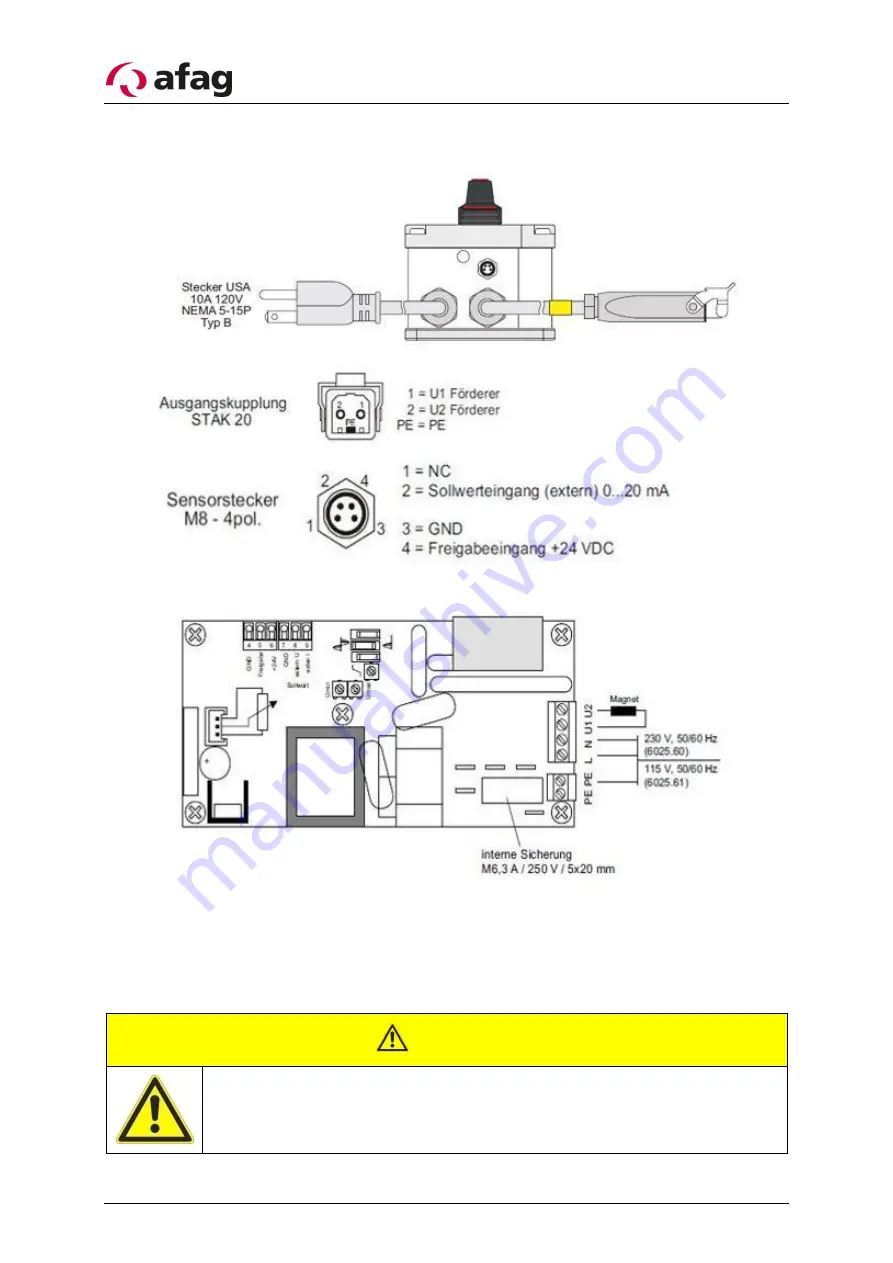
Страница 9: ...tions 3 1 Installing the unit There are two holes on the underside for mounting the controller The holes are sep arated from the interior of the housing See Figure 1 3 2 Connection possibilities Type 230V 50Hz Figure 2 Connection possibilities ...
Страница 10: ...Page 10 04 03 2020 R02 1 Type 115V 60Hz CAUTION Jumpers may only be inserted for the respective application oth erwise this may lead to a malfunction of or damage to the p c b ...
Страница 11: ...ge 11 4 Operating instructions Standard settings can be made without removing the front panel The setting up components are accessed by removing the small cover on the right hand side of the front panel Figure 3 Settings ...
Страница 12: ...115V Units Umin 20 V Umax 105 V 4 2 Setpoint source Selection Setpoint Potentiometer or Setpoint external control current 0 20 mA 4 3 Half and full wave The correct setting of the vibrating frequency is particularly important because the wrong frequency could cause the magnet to be overloaded This setting is made with an internal slider switch The mechanical frequency of the feed system must be ch...
Страница 13: ...requency and the mains voltage must conform to one another Umax trimmer setting too low set Umax Conveyor vibrates too much mag net knocking noises Incorrect oscillation frequency setting CAU TION Magnet may have been destroyed by overheating or mechanically damaged by knocking against something Umax trimmer setting too high reset Umax if necessary Magnet heats up Incorrect mains voltage for magne...
Страница 14: ...0 Sales sales afag com www afag com Switzerland Afag Automation AG Zuführtechnik Fiechtenstrasse32 CH 4950 Huttwil Tel 41 0 62 959 86 86 Fax 41 0 62 959 87 87 7 Disposal Controllers that are no longer in use should not be disposed of as complete units but dismantled into separate materials and recycled Non recyclable components must be disposed of correctly ...