24
EU-20-OI-v-1.2 gb. 28.07.14.docx
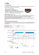
3.12 LED-Display
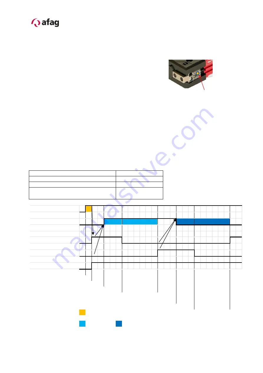
The integrated indicator light shows the status of the gripper actuator. A yellow LED on the
board is visible through the housing opening:
- No light = no supply voltage
- Permanent light = standard operation
- Flashing with 5 Hz = serial interface active
- Error code 1; 2 pulses: does not leave the Start position
- Error code 2; 3 pulses: power in limit positions not reached
- Error code 3; 4 pulses: short circuit at the outputs
Operating modes
(initial mode)
When the supply voltage is applied (Power ON), the controller initializes automatically with-
out moving the gripper and remembers the last conditions of the inputs and outputs.
When this process has been completed successfully the last status is displayed at the two
digital outputs and the yellow LED lights permanently.
A potential which was changed in the meantime (status change) is executed immediately on
the DI.
Standard mode (retracting/extending)
The output signals are no longer inverted at the end of a cycle but the applied signal drops
out directly after start of the movement and the following signal is received only at the end of
the movement.
Position when switching off
retracted
Last status of DI
Low
Status of DI when switching on
Low
24VDC supply
DI control signal
retracted DO1
DO2 extended
LED
Start of initialization
End of initialization
Start extending
Leave initial position
extended
Start retracting
Initialize
Leave initial position
retracted
Extend
Retract
Содержание 50346017
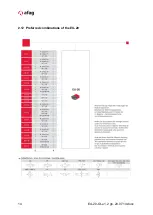
Страница 14: ...14 EU 20 OI v 1 2 gb 28 07 14 docx 2 12 Preferred combinations of the EU 20 ...
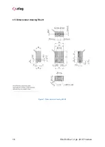
Страница 18: ...18 EU 20 OI v 1 2 gb 28 07 14 docx 3 5 Dimensional drawing EU 20 Figure 3 Dimensional drawing EU 20 ...
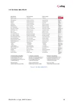
Страница 19: ...EU 20 OI v 1 2 gb 28 07 14 docx 19 3 6 Technical data EU 20 Figure 3 Technical data EU 20 ...

