background image

Installation, Operation & Maintenance Manual

IM-166

9

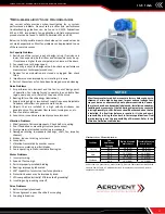
Fan Installation – Factory Assembled Units 

(refer to lifting/safety section)

All fan impellers are statically and dynamically balanced using state of the art equipment in the factory. Final trim balancing is 

performed on factory assembled fans, unless the specified electrical characteristics of the motor are outside the limits of the factory 

test equipment. If the motor and drives are supplied, the complete assembly is run tested and balanced. Infrequently, fans are 

supplied with unusual electrical characteristics and cannot be tested with the motor. In this situation the fans are run and balanced 

using a factory driver. Likewise, if motors and/or drives are not supplied, the fan is tested with the factory driver. Final balancing, at 

the buyer’s expense, should be performed in the field after the motor and/or drives are installed. This service is available from TCF, 

otherwise this should be entrusted to a qualified technician.

Follow proper handling instructions as given earlier.

1.  Move the fan to the final mounting position.
2.  Remove skid, crates and packing materials carefully.
3.  Attach vibration isolators (if used) to appropriate mounting 

locations on fan. Locate fan in position using lifting 

instructions on page 5.

4.  Place the fan on mounting structure. Carefully level the unit 

on the foundation and shim as necessary using stainless 

steel shims on both sides of each anchor bolt. Back off 

leveling nuts if used. Be careful not to force the fan to the 

mounting structure/foundation. This may cause the bearings 

to become misaligned or pinched causing vibration and 

premature failure.

5.  Check the alignment of the bearings. Shim or reposition the 

bearings if necessary.

6.  Check alignment of sheaves on belt driven fans.
7.  Check tension of belts to see if it is sufficient. Sheaves on 

belt driven fans are often provided with taper lock bushings. 

When tightening bushing bolts, proceed in a progressive 

manner to avoid cocking the tapered surfaces between the 

bushing and the sheave. Torque per tables on the right.


8.  Check the tightness of the impeller on the shaft. Check the 

tightness of foundation bolts, motor bolts, sheaves and 

bearings. Make sure there is no rubbing or binding and that 

the impeller-inlet cone clearances and overlap are correct.

9.  Check that bearings are fully lubricated. For spherical roller 

bearings with split pillow block housings, the bottom half 

of the housings should be 1/3 full of grease. For oil lube 

bearings, the oil level should reach the midpoint of the 

bottom roller or ball.

10.  Install any accessories shipped loose from the factory.

The above torque values are for nonlubricated fasteners and Browning 

Bushings. For bearing set screws, use manufacturer’s recommendations. 

If other bushings are used, utilize bushing manufacturer's specifications.

Tolerance: +/-


5%

For impeller set screws use Grade 2 values.

SIZE

FASTENER - TIGHTENING TORQUE (Ft. Lbs.)

GRADE 2

GRADE 5

GRADE 8

#10

1

4

-20

5.5

8

12

5

16

-18

11

17

25

3

8

-16

22

30

45

7

16

-14

30

50

70

1

2

-13

55

75

110

9

16

-12

5

8

-11

100

150

220

3

4

-10

170

270

380

7

8

-9

165

430

600

1-8

250

645

900

1

1

4

-7

500

1120

1500

SIZE

TAPER BUSHINGS - TIGHTENING TORQUE (Ft. Lbs.)

SPLIT

QD 

FOR DRIVE

IN IRON

IN ALUM. HUB

#10

5

1

4

-20

7.9

7.5

9

5

16

-18

16

13

15

3

8

-16

29

24

30

7

16

-14

1

2

-13

70

60

9

16

-12

75

5

8

-11

135

3

4

-10

7

8

-9

1-8

1

1

4

-7

Tightening Torque

Carefully level the fan on the foundation

Click To View Our

Sheave Installation video

Содержание IM-166

Страница 1: ...t www aerovent com REVIEW AMCA PUBLICATION 410 PRIOR TO INSTALLATION Table of Contents Fan Arrangements 2 Exploded View 2 Impeller Nomenclature 3 Impeller Rotation 3 Safety Hazard Warnings 4 Shipping Receiving 4 Handling 5 Unit Storage 6 Foundations and Supporting Structures 7 8 Fan Installation Factory Assembled Units 9 Bearing Installation 10 Safety Bearing Lubrication Instructions 11 Drive Moun...

Страница 2: ...ement 3 Belt Driven Arrangement 4 Direct Drive Exploded View Arrangement 9 Belt Driven Inlet Funnel Sheave Pulley Impeller Bearing Housing With End Cover Plate Belt Tube Straightening Vanes Discharge Cone Belt Tube Seal Removable Housing Motor Mount Bearings Shaft Motor Belt ...

Страница 3: ...lation Operation Maintenance Manual IM 166 3 Impeller Cone End Ring Shroud Front Plate Back Plate Blade Impeller Nomenclature AIRFLOW Impeller Rotation CLOCKWISE CW example shown Rotation View From Drive Side ...

Страница 4: ...ve clothing eye protection ear protection respiratory equipment hand and foot protection when installing or servicing the fan Always use caution when entering a fan s air path High velocity airflow can cause you to lose your balance Motor bearings and drives can be hot and similarly if the fan is subject to processes that are hot the fan housing could be hot Fans are often used to move hazardous m...

Страница 5: ...f the impeller as this may distort the impeller Take care not to damage the shaft where the impeller or bearings will be mounted Never lift or support the assembly by the impeller Always support the assembly by the shaft when lifting or storing see the section regarding proper storage of equipment Do not support the shaft or the impeller on the housing sides See the Fan Installation section for ad...

Страница 6: ... is to be stored for a prolonged period The drives should be labeled for service and stored in a dry place Belts should be removed coiled without kinks placed in a heavy carton and stored in a dry well ventilated place To prevent belt deterioration storage conditions should not exceed 85 F and 70 humidity If belts show signs of deterioration they should be replaced prior to startup Motors should b...

Страница 7: ...r strength is not sufficient to ensure operation at low vibration levels Supports for suspended fans must be cross braced to prevent side sway Structural resonance should be at least 20 from fan operating speed Vibration isolators may help block the transmission of vibration into a structure Any ducting should have independent support do not use the fan to support ducting Flexible connections are ...

Страница 8: ...o threaded rod to provide clearance 3 Hanger rods nuts and washers supplied by customer Typical Vertical Mounting with Vibration Hangers 1 2 6 3 4 5 7 ITEM QTY DESCRIPTION 01 1 Fan 02 4 Anchor Bolt 03 8 Hex Nut 04 8 Washer NOTE 1 Anchor bolts and hardware supplied by customer 1 2 3 4 Typical Horizontal Mounting to Rigid Foundation ITEM QTY DESCRIPTION 01 1 Fan 02 See Note Lag Bolt 03 1 Stack Cap O...

Страница 9: ...remature failure 5 Check the alignment of the bearings Shim or reposition the bearings if necessary 6 Check alignment of sheaves on belt driven fans 7 Check tension of belts to see if it is sufficient Sheaves on belt driven fans are often provided with taper lock bushings When tightening bushing bolts proceed in a progressive manner to avoid cocking the tapered surfaces between the bushing and the...

Страница 10: ...al 4 Unless the user orders differently bearings are lubricated in the factory with a lithium complex NLGI grade 2 grease Refer to the bearing lubrication schedule on the next page Spherical Roller Bearings with Split Pillow Block Housings 1 The bearings should be disassembled taking care not to interchange parts between bearings Tops of housings are not interchangeable with the bottom half pillow...

Страница 11: ... the general assembly drawing supersede requirements found here Fans with Ball Bearings Relubrication Schedule Weeks Ball Bearing Pillow Blocks Shaft DIA Speed RPM 500 1000 1500 2000 2500 3000 3500 4000 4500 1 2 thru 111 16 13 45 6 6 5 3 3 2 2 2 1 115 16 thru 27 16 50 60 6 5 4 2 2 1 1 1 1 211 16 thru 215 16 65 75 5 4 3 2 1 1 1 37 16 thru 315 16 90 100 4 3 2 1 1 Suggested lubrication interval under...

Страница 12: ...e runout or a bent shaft Unless there is a bent shaft runout can be corrected by adjustments to the bolt torque of the taper bushing 3 Install and tighten the belts Run the drive for a few minutes to seat the belts When fitting the belts adjust the motor position to fit on the belts Do not use a pry bar as this may damage the belt cords Tighten the belts to the proper tension Ideal tension is just...

Страница 13: ...y of the fan Periodic inspections lubrication and observations of sound and vibration will help prolong the life of the fan If changes are noted check bolt tightness foundation integrity cleanliness of the impeller and or motor bearing lubrication and drive components Always keep records of the maintenance that is performed Motor Maintenance The three basic rules of motor maintenance are 1 Keep th...

Страница 14: ...he grease expelled from unit ball or roller bearings at the time of relubrication is the best guide as to whether regreasing intervals and amount of grease added should be altered Spherical roller bearings with split pillow block housings should not be lubricated until grease purges or overheating may result Follow the lubrication interval and amount noted in the Bearing Installation section Spher...

Страница 15: ... foundation Duct Connections refer to safety section The fan support structure is normally not designed to carry loads imposed by the weight of ducts silencers stacks etc Supporting these loads on the fan can cause housing distortion and may cause performance or vibration problems Use of flexible connections is recommended for all fans and imperative when using vibration isolation or handling high...

Страница 16: ...0 330 365 402 445 490 542 600 660 730 A 12 25 15 00 16 50 18 25 20 00 22 25 24 50 27 00 30 00 33 00 36 50 40 25 44 50 49 00 54 25 60 00 66 00 73 00 80 75 89 00 B 0 31 0 38 0 44 0 56 0 63 0 69 0 75 0 88 0 97 1 06 0 94 1 03 1 13 1 25 1 38 1 56 1 69 1 88 2 09 2 28 C 4 20 5 13 5 64 6 19 6 75 7 56 8 31 9 13 10 19 11 19 12 38 13 63 15 13 16 63 18 38 20 25 22 31 24 63 27 25 30 00 Model AMX ...

Страница 17: ...heck belt or coupling 2 Poor foundation or mounting structure resonances 3 Foreign material attached to rotating components 4 Damaged rotating components bearings shaft fan impeller sheaves 5 Broken loose or missing set screws 6 Loose bolts 7 Vibration transmitted by another source 8 Water accumulating in airfoil blades 9 Fan is operating in stall or unstable flow region Motor Problems 1 Incorrect...

Страница 18: ...olts tight Check to see if the fan is distorted by the foundation and or ductwork Note Applies to direct or isolation mount Check fan interior for debris and standing water Fan Impeller Impeller clearance checked Impeller overlap checked Fasteners tight Impeller rotates freely Springs if equipped Springs adjusted properly Flex joints allow movement Electrical conduit allows movement Bearings Beari...

Страница 19: ...Installation Operation Maintenance Manual IM 166 19 Date Completed Maintenance Performed By Comments Model Number__________________________ Serial Number __________________________ Fan Maintenance Log ...

Страница 20: ...WWW AEROVENT COM 5959 Trenton Lane N Minneapolis MN 55442 Phone 763 551 7500 Fax 763 551 7501 2009 2022 Aerovent ...

Отзывы: