background image

2.2. Securing the Hexapod to the Mounting Surface

DANGER: Mechanical Hazard!

Personnel must be made aware of the mechanical hazards during set up or when you
do service to the stage.

l

Do not manually move the hexapod if it is connected to a power source.

l

The stage must be mounted securely. Improper mounting can result in injury and
damage to the equipment.

l

When you move the tabletop manually to do maintenance, this could expose the
operator to pinch points. Refer to

Pinch Points

on

Page 12

.

The mounting surface must be flat and have adequate stiffness to achieve the maximum
performance from the hexapod. When it is mounted to a non-flat surface, the stage can be distorted
while the mounting screws are tightened. This distortion will decrease overall accuracy. Adjustments
to the mounting surface must be done before the stage is secured.

Inspect the mounting surface for dirt or unwanted residue and clean if necessary. Use precision
flatstones on the mounting surface to remove any burrs or high spots. Clean the mounting surface
with a lint-free cloth and acetone or isopropyl alcohol and allow the cleaning solvent to completely
dry. Gently place the stage on the mounting surface.

IMPORTANT

: The hexapod is precision machined and verified for flatness at the

factory.

l

Do not machine the hexapod housing. If you must machine a surface to achieve a
required flatness, machine the mating mounting surface.

l

Keep the use of shims to a minimum when you mount the hexapod to the mounting
surface. The use of shims could reduce the rigidity of the system.

IMPORTANT

: To maintain accuracy, the mounting surface must be flat to within 0.0127

mm over the contact area.

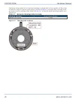
A minimum of six M8 mounting screws are required to mount the hexapod to the mounting surface.
Refer to

Figure 2-2

or

Section 2.1. Dimensions

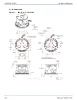
for mounting locations and

Table 2-1

for tightening

torque values.

Hardware Manual

HEX500-350HL

www.aerotech.com

25

Содержание HexGen HEX500-350HL

Страница 1: ...Revision 2 01 HexGen HEX500 350HL Hexapod Six DOF Positioning System HARDWARE MANUAL...

Страница 2: ...spare or replacement parts To get help immediately contact a service office or your sales representative Include your customer order number in your email or have it available before you call This man...

Страница 3: ...on 20 1 3 1 Hexapod Axes 20 1 3 2 Strut Limits and Hexapod Range 20 1 3 3 Homing 21 Chapter 2 Mechanical Specifications and Installation 23 2 1 Dimensions 24 2 2 Securing the Hexapod to the Mounting S...

Страница 4: ...Load Capabilities 27 Figure 2 4 HEX500 350HL Horizontal Load Capabilities 28 Figure 2 5 HEX500 350HL Inverted Load Capabilities 28 Figure 3 1 Motor and Feedback Wiring E2 Connector 33 Figure 3 2 Moto...

Страница 5: ...tion Motor and Feedback Pinout 32 Table 3 4 Mating Connector Part Numbers 32 Table 3 5 Hall Effect Sensor Specifications 35 Table 3 6 Thermistor Specifications 35 Table 3 7 Encoder Specifications 35 T...

Страница 6: ...ipment into service until the machinery into which it is to be incorporated or of which it is to be a component has been found and declared to be in conformity with the provisions of the Directive 200...

Страница 7: ...y Basic concepts general principles for design EN 60204 1 2010 Safety of Machinery Electrical equipment of machines Part 1 General requirements and furthermore declares that it is not allowed to put t...

Страница 8: ...by the manufacturer l The protection provided by the equipment could be impaired l The life expectancy of the product could be decreased Safety notes and symbols are placed throughout this manual to w...

Страница 9: ...equipment l All service and maintenance must be done by approved personnel l Use this product only in environments and operating conditions that are approved in this manual l Never install or operate...

Страница 10: ...l Do not connect or disconnect stage motor interconnections while connected to a live electrical power source l Before you set up or do maintenance disconnect electrical power l It is the responsibili...

Страница 11: ...re could exceed 70 C in some applications l Do not touch the stage motor frame while it is in operation l Wait until the stage motor has cooled before you touch it Figure 1 Motor Location DANGER Risk...

Страница 12: ...l Hazard l System travel can cause crush shear or pinch injuries l Only trained operators should operate this equipment l Do not put yourself in the travel path of machinery l Restrict access to all m...

Страница 13: ...quipment and instrumentation is wrapped in antistatic material and packaged with desiccant Ensure that the antistatic material is not damaged during unpacking DANGER Lifting Hazard Use care when you m...

Страница 14: ...ed at Aero tech l Remove the shipping brackets before you operate the hexapod Retain them for future use Each HEX500 350HL has a label that lists the system part number and serial number These numbers...

Страница 15: ...t can move manually without electrical power connected l When the shipping brackets are removed the operator could be exposed to pinch points Figure 2 1 Lifting and Shipping Brackets Storage Store the...

Страница 16: ...This page intentionally left blank HEX500 350HL Hardware Manual 16 www aerotech com...

Страница 17: ...platform The struts attach only to the joints of the base and platform The cables exit out of the back of the base These six cables connect the hexapod to the controller refer to the Section 3 2 Figu...

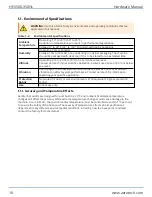
Страница 18: ...ation Use the system in a low vibration environment Excessive floor or acoustical vibration can affect system performance Contact Aerotech for information regarding your specific application Protectio...

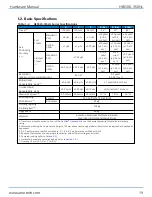
Страница 19: ...15 m 0 5 rad 0 1 arc sec Maximum Speed 4 50 mm s 50 mm s 25 mm s 10 s 10 s 20 s Load Capacity All Positions 5 Vertical 200 kg Push 120 kg Pull Horizontal 35 kg Holding Capacity De Energized 6 165 kg...

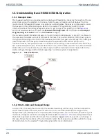
Страница 20: ...nal axes are oriented in the same direction as the translational axes and positive rotation is clockwise when looking in the direction of the axis The A axis rotates about the X axis B rotates about t...

Страница 21: ...tions to be accurate The home sequence involves moving each strut to its shortest position and then returning to the center of travel Be sure that there are no crash conditions before homing Refer to...

Страница 22: ...This page intentionally left blank HEX500 350HL Hardware Manual 22 www aerotech com...

Страница 23: ...our system l To prevent injury to you and damage to the equipment obey the precautions in this manual l All specifications and illustrations are for reference only and were complete and accurate as of...

Страница 24: ...2 1 Dimensions Figure 2 1 HEX500 350HL Dimensions HEX500 350HL Hardware Manual 24 www aerotech com...

Страница 25: ...ting surface for dirt or unwanted residue and clean if necessary Use precision flatstones on the mounting surface to remove any burrs or high spots Clean the mounting surface with a lint free cloth an...

Страница 26: ...in Table 2 1 are typical values and may not be accurate for your mounting surface Refer to Section 2 1 for specific model mounting locations and dimensions Table 2 1 Hexapod to Mounting Surface Hardwa...

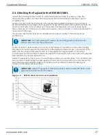
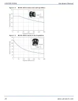
Страница 27: ...should be flat within 0 0127 mm over the contact area Loads should be mounted close to the center of the hexapod if possible to reduce offset loading The maximum load is based on the distance from th...

Страница 28: ...Figure 2 4 HEX500 350HL Horizontal Load Capabilities Figure 2 5 HEX500 350HL Inverted Load Capabilities HEX500 350HL Hardware Manual 28 www aerotech com...

Страница 29: ...nd meeting all safety and compliance requirements when they integrate the HEX500 350HL into a completed system Failure to do so could expose the operator to electrical or mechanical hazards Electrical...

Страница 30: ...meet all safety and compliance requirements when they integrate the HEX500 350HL into a completed system IMPORTANT The protective ground connection must be properly installed to minimize the possibili...

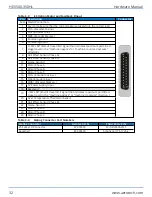
Страница 31: ...to the correct jack 12 Hall Effect Sensor Phase A 13 Hall Effect Sensor Phase B 14 COS Encoder Cosine 15 SIN Encoder Sine 16 CLK Absolute Encoder Clock 17 5V Power Supply Input 18 Stage ID 19 DATA Abs...

Страница 32: ...C 10 Frame Ground 11 Motor Phase A 12 Motor Phase B 13 Motor Phase C 14 COS Encoder Cosine 15 SIN Encoder Sine 16 MRK Encoder Marker 17 5V Power Supply Input 18 Reserved 19 CW LMT End of travel limit...

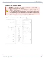
Страница 33: ...ty requirements l It is the responsibilty of the system integrator or qualified installer to determine and meet all safety and compliance requirements when they integrate the HEX500 350HL into a compl...

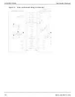
Страница 34: ...Figure 3 2 Motor and Feedback Wiring E3 Connector HEX500 350HL Hardware Manual 34 www aerotech com...

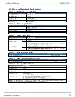
Страница 35: ...onal E3 Sinusoidal Type Incremental Rotary Encoder 1 Vpk pk into 120 load differential signals SIN SIN COS and COS Table 3 8 Rotary Encoder Resolution Fundamental Signal Period Fundamental Resolution...

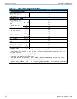
Страница 36: ...ation system cooling conditions and ambient temperature 2 Values shown 75 C rise above a 25 C ambient temperature with housed motor mounted to a 250 mm x 250 mm x 6 mm aluminum heat sink 3 Peak force...

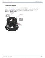
Страница 37: ...is dictated by the hexapod wiring refer to Section 3 5 for Motor and Feedback phasing information Programming direction of a stage is set by the controller that is used to move the stage Programming...

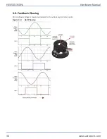
Страница 38: ...3 5 Feedback Phasing Motor phase voltage is measured relative to the virtual wye common point Figure 3 4 Hall Phasing HEX500 350HL Hardware Manual 38 www aerotech com...

Страница 39: ...Figure 3 5 Encoder Phasing Reference Diagram Standard Hardware Manual HEX500 350HL www aerotech com 39...

Страница 40: ...This page intentionally left blank HEX500 350HL Hardware Manual 40 www aerotech com...

Страница 41: ...sconnect the electrical power l Restrict access to the hexapod when it is connected to a power source 4 1 Service and Inspection Schedule Inspect and clean the HEX500 350HL once per month A longer or...

Страница 42: ...bearings The motor is completely non contact and requires no lubrication Only use the grease specified Table 4 1 Grease Specifications Location Grease Ball Joints Kluberplex BEM 34 132 Lubrication Pro...

Страница 43: ...troller Fault Check the controller for faults Refer to the controller and software documentation Strut moves uncontrollably Encoder Signal Connection or the Motor Signal Connection Check to make sure...

Страница 44: ...This page intentionally left blank HEX500 350HL Hardware Manual 44 www aerotech com...

Страница 45: ...aterials Authorization RMA number must accompany any returned product s The RMA number may be obtained by calling an Aerotech service center or by submitting the appropriate request available on our w...

Страница 46: ...iods then special rates apply If during the on site repair it is determined the problem is not warranty related then the terms and conditions stated in the following On Site Non Warranty Repair sectio...

Страница 47: ...History Revision Description 2 01 l General update safety l Added UKCA Declaration of Incorporation 2 00 General update 1 01 Updated encoder specifications 1 00 New Manual Hardware Manual HEX500 350HL...

Страница 48: ...This page intentionally left blank HEX500 350HL Hardware Manual 48 www aerotech com...

Страница 49: ...rs Specifications 35 Handling 13 Horizontal Load Capabilities 28 Humidity 18 I Incremental Encoder 35 Incremental Rotary Encoder 35 inspect 41 Inspection 41 Inverted Load Capabilities 28 isopropyl alc...

Страница 50: ...stage distortion 25 Storage 13 T Table of Contents 3 Temperature Effects 18 Thermistor Specifications 35 U Use 18 V Vertical Load Capabilities 27 Vibration 18 W Warnings 8 Warranty and Field Service 4...

Отзывы: