BM/BMS Series Hardware Manual
Introduction
www.aerotech.com 1-5
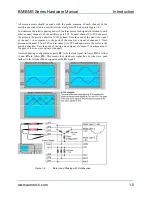
All measurements should be made with the probe common of each channel of the
oscilloscope connected to a neutral reference test point (TP4, shown in Figure 1-4).
To determine the relative phasing/order of the three motor lead signals in relation to each
other, connect channel 1 of the oscilloscope to TP1. Connect channel 2 to TP2 and move
the motor in the positive direction (CW) by hand. Note the peak of the sine wave signal
of channel 1 in comparison to the peak of the sine wave signal of channel 2. Next,
disconnect channel 2 from TP2 and reconnect it to TP3 and again move the motor in the
positive direction. Note the peak of the sine wave signal of channel 3 in comparison to
the peak of the sine wave signal of channel 1.
Aerotech phasing configuration expects
Ø
C to be the lead signal (in time),
Ø
B to follow
it, and
Ø
A to follow
Ø
B. This means that whichever signal has its sine wave peak
farthest to the left should be designated as the
Ø
C signal.
Figure 1-4:
Motor Lead Phasing with Oscilloscope
Содержание BM Series
Страница 6: ...Table of Contents BM BMS Series Hardware Manual iv www aerotech com...
Страница 8: ...List of Figures BM BMS Series Hardware Manual vi www aerotech com...
Страница 10: ...List of Tables BM BMS Series Hardware Manual viii www aerotech com...
Страница 12: ...Declaration of Conformity BM BMS Series Hardware Manual x www aerotech com...
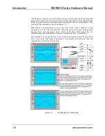
Страница 20: ...Introduction BM BMS Series Hardware Manual 1 8 www aerotech com Figure 1 6 Resolver and Motor Phasing...
Страница 50: ...Appendix A BM BMS Series Hardware Manual A 8 www aerotech com...
Страница 56: ...Index BM BMS Series Hardware Manual Index 2 www aerotech com...
Страница 58: ......


