background image

Chapter 2: Installation

The gimbal installation must be in accordance with the instructions provided by this
manual and any accompanying documentation. Failure to follow these instructions
could result in injury or damage to the equipment.

2.1. Dimensions

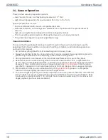
Figure 2-1:

AOM360D-200 Dimensions

Hardware Manual

AOM360D

www.aerotech.com

21

Содержание AOM360D Series

Страница 1: ...Revision 2 00 AOM360D Series Direct Drive Gimbals HARDWARE MANUAL ...

Страница 2: ...d spare or replacement parts To get help immediately contact a service office or your sales representative Include your customer order number in your email or have it available before you call This manual contains proprietary information and may not be reproduced disclosed or used in whole or in part without the express written permission of Aerotech Inc Product names mentioned herein are used for...

Страница 3: ...s 17 1 4 Vacuum Operation 18 1 5 Export Restrictions 19 Chapter 2 Installation 21 2 1 Dimensions 21 2 2 Securing the Base to the Mounting Surface 25 2 3 Attaching the Payload to the Stage 27 Chapter 3 Electrical Installation 29 3 1 Motor and Feedback Connectors 30 3 2 Motor and Feedback Wiring 33 3 3 Hall Thermistor Inductosyn and Limits Specifications 35 3 4 Limits Marker and Machine Direction 38...

Страница 4: ... 400 Dimensions 23 Figure 2 4 AOM360D 500 Dimensions 24 Figure 2 5 View of AOM360DShowing Mounting Holes 26 Figure 3 1 Motor and Feedback Wiring AZ EL 33 Figure 3 2 Feedback Interconnection Drawing 34 Figure 3 3 Machine Direction 38 Figure 3 4 Hall Phasing Diagram 39 AOM360D Hardware Manual 4 www aerotech com ...

Страница 5: ...r 31 Table 3 3 19 Pin Feedback Connector Pinouts AZ and EL 32 Table 3 4 Mating Connector Part Numbers for the 19 Pin Feedback Connector 32 Table 3 5 Hall Effect Sensor Specifications 35 Table 3 6 Thermistor Specifications 35 Table 3 7 Inductosyn Specifications 35 Table 3 8 Limit Switch Specifications 35 Table 3 9 S 180 44 EL and S 180 69 AZ Rotary Motor Specifications 200 and 300 options 36 Table ...

Страница 6: ...t into service until the machinery into which it is to be incorporated or of which it is to be a component has been found and declared to be in conformity with the provisions of the Directive 2006 42 EC and with national implementing legislation for example as a whole including the equipment referred to in this Declaration This is to certify that the aforementioned product is in accordance with th...

Страница 7: ...gn EN 60204 1 2010 Safety of machinery Electrical equipment of machines Part 1 General requirements and furthermore declares that it is not allowed to put the product into service until the machinery into which it is to be incorporated or of which it is to be a component has been found and declared to be in conformity with the provisions of the Supply of Machinery Safety Regulations 2008 UK Legisl...

Страница 8: ...d by the manufacturer l The protection provided by the equipment could be impaired l The life expectancy of the product could be decreased Safety notes and symbols are placed throughout this manual to warn you of the potential risks at the moment of the safety note or if you fail to obey the safety note Shock Electrocution Hazard Pinch Shear or Crush Hazard General Conditional Awareness Rotational...

Страница 9: ...e this equipment l All service and maintenance must be done by approved personnel l Use this product only in environments and operating conditions that are approved in this manual l Never install or operate equipment that appears to be damaged l Make sure that the product is securely mounted before you operate it l Use care when you move the AOM360D or you could negatively affect the per formance ...

Страница 10: ...ed l Do not connect or disconnect stage motor interconnections while connected to a live electrical power source l Before you set up or do maintenance disconnect electrical power l It is the responsibility of the End User System Integrator to make sure that stages are properly connected and grounded per Engineering Standards and applicable safety requirements l It is the responsibility of the End ...

Страница 11: ...e motor frame temperature could exceed 70 C in some applications l Do not touch the stage motor frame while it is in operation l Wait until the stage motor has cooled before you touch it DANGER Risk of Explosive Atmosphere l Standard Aerotech stage motors are not rated for applications with explosive atmospheres such as airborne dust or combustible vapors l Do not operate stage motors outside of A...

Страница 12: ...echanical Hazard l System travel can cause crush shear or pinch injuries l Only trained operators should operate this equipment l Do not put yourself in the travel path of machinery l Restrict access to all motor and stage parts o when the system moves under power during normal operation for example o when the system is moved manually during the installation process or when you do maintenance for ...

Страница 13: ...and record the information for later reference Unpacking and Handling It is the responsibility of the customer to safely and carefully lift and move the gimbal IMPORTANT All electronic equipment and instrumentation is wrapped in antistatic material and packaged with desiccant Ensure that the antistatic material is not damaged during unpacking DANGER Lifting Hazard Use care when you move the AOM360...

Страница 14: ... These numbers contain information necessary for maintenance or system hardware and software updates Locate this label and record the information for later reference Storage Store the gimbal in the original shipping container If the original packaging included ESD protective packaging make sure to store the gimbal in it The storage location must be dry free of dust free of vibrations and flat Refe...

Страница 15: ...e 1 1 Model Numbers and Ordering Options AOM360D Optical Mount Cell Size Required 200 200 mm diameter cell 300 300 mm diameter cell 400 400 mm diameter cell 500 500 mm diameter cell Hardware Manual AOM360D www aerotech com 15 ...

Страница 16: ...desiccant if it is to be stored for an extended time Altitude Operating 0 m to 2 000 m 0 ft to 6 562 ft above sea level Contact Aerotech if your specific application involves use above 2 000 m or below sea level Vibration Use the system in a low vibration environment Floor or acoustical vibration can affect system performance Contact Aerotech for information regarding your specific application Pro...

Страница 17: ...arameters Diameter 203 2 mm 304 8 mm 406 6 mm 508 0 mm Thickness 40 6 mm 53 3 mm 63 5 mm 88 9 mm Weight 20 0 kg 20 0 kg 50 0 kg 50 0 kg Axis Wobble Azimuth 14 6 µrad 3 arc sec Elevation 24 3 µrad 5 arc sec Orthogonality 48 5 µrad 10 arc sec 12 µrad 2 arc sec optional Mass 84 kg 91 kg 208 kg 234 kg AZ Inertia 1 62 kg m2 2 5 kg m2 9 kg m2 12 53 kg m2 EL Inertia 0 019 kg m2 0 105 kg m2 0 27 kg m2 0 9...

Страница 18: ...imbal in a clean environment and use powder free polyethylene gloves to prevent any contaminants from adhering to the surface of the gimbal 3 During installation use cleaned vented stainless steel fasteners to secure the gimbal 4 Reduced air pressure eliminates significant convective heat transfer This coupled with the viscous vacuum compatible lubricants could result in excessive motor operating ...

Страница 19: ...ment export regulations If you are from a non US country and wish to make a purchase contact Aerotech to determine if an export license is required People in countries embargoed by the United States cannot purchase and import one of these products Hardware Manual AOM360D www aerotech com 19 ...

Страница 20: ...This page intentionally left blank AOM360D Hardware Manual 20 www aerotech com ...

Страница 21: ...ance with the instructions provided by this manual and any accompanying documentation Failure to follow these instructions could result in injury or damage to the equipment 2 1 Dimensions Figure 2 1 AOM360D 200 Dimensions Hardware Manual AOM360D www aerotech com 21 ...

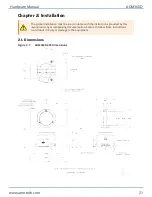
Страница 22: ...Figure 2 2 AOM360D 300 Dimensions AOM360D Hardware Manual 22 www aerotech com ...

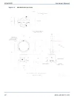
Страница 23: ...Figure 2 3 AOM360D 400 Dimensions Hardware Manual AOM360D www aerotech com 23 ...

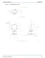
Страница 24: ...Figure 2 4 AOM360D 500 Dimensions AOM360D Hardware Manual 24 www aerotech com ...

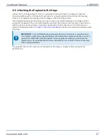
Страница 25: ...ohol and allow the cleaning solvent to completely dry Gently place the stage on the mounting surface IMPORTANT The gimbal is precision machined and verified for flatness at the factory l Do not machine the gimbal housing If you must machine a surface to achieve a required flatness machine the mounting surface l Keep the use of shims to a minimum when you mount the gimbal to the mounting surface Th...

Страница 26: ...Figure 2 5 View of AOM360DShowing Mounting Holes AOM360D Hardware Manual 26 www aerotech com ...

Страница 27: ...umentation Document all results for future reference For information on electrical installation refer to Chapter 3 Electrical Installation and the documentation delivered with the stage IMPORTANT If your AOM360D was purchased with Aerotech controls it could have been tuned with a representative payload based on the information provided at the time of order If you start the AOM360D without a payloa...

Страница 28: ...This page intentionally left blank AOM360D Hardware Manual 28 www aerotech com ...

Страница 29: ...l safety and compliance requirements when they integrate the AOM360D into a completed system Electrical installation requirements will depend on the ordered product options Installation instructions in this section are for Aerotech products equipped with standard Aerotech motors intended for use with an Aerotech motion control system Contact Aerotech for further information on products that are ot...

Страница 30: ...or frame ground protection only Additional grounding and safety precautions are required for applications requiring access to the stage while it is energized The System Integrator or qualified installer is responsible for determining and meeting all safety and compliance requirements necessary for the integration of this stage into the final application DANGER Electrical Shock Hazard l The protect...

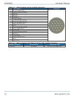
Страница 31: ...t Sensor Phase C R Motor Halls 5 V common ground S CCW LMT End of travel limit signal that indicates maximum permitted stage travel in the machine negative or machine counter clockwise direction 2 T Limits 5 V common ground U Motor Phase C V Reserved W Reserved X Stage Frame Ground PE Y Reserved Z Over Temperature Thermistor Sensor a Home limit connected internally to Pin S 3 b Signal Shield c Mot...

Страница 32: ... H COS Encoder Cosine J SIN Encoder Sine K REF L Supply common ground M 12 V supply input N Reserved P Signal 2 Signal 4 Shield R Signal 4 S Sine Shield T SIN Encoder Sine U REF V Ref Shield Table 3 4 Mating Connector Part Numbers for the 19 Pin Feedback Connector Mating Connector Aerotech P N Third Party P N Connector ECK00619 ITT Cannon KPT06J14 19S AOM360D Hardware Manual 32 www aerotech com ...

Страница 33: ...3 2 Motor and Feedback Wiring Shielded cables are required for the motor and feedback connections Figure 3 1 Motor and Feedback Wiring AZ EL Hardware Manual AOM360D www aerotech com 33 ...

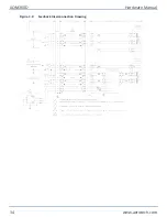
Страница 34: ...Figure 3 2 Feedback Interconnection Drawing AOM360D Hardware Manual 34 www aerotech com ...

Страница 35: ...2 VDC 1 0 8 A typical Signals Differential Sine Wave SIN COSIN frequency amplitude and phasing optimized at the factory Table 3 8 Limit Switch Specifications Specification Supply Voltage 5 V 5 Supply Current 25 mA Output Type Open Collector Output Voltage 5 V Output Current 10 mA sinking Output Polarity Factory Configured Normally Closed NC l Sinks current to ground Logic 0 when not in limit l Hig...

Страница 36: ... 82 0 67 Number of Poles 18 18 1 Performance is dependent upon heat sink configuration system cooling conditions and ambient temperature 2 Values shown 75 C rise above a 25 C ambient temperature with housed motor mounted to a 330 mm x 330 mm x 13 mm aluminum heat sink 3 Peak force assumes correct rms current consult Aerotech 4 Torque constant and motor constant specified at stall 5 All performance...

Страница 37: ...0 340 Thermal Resistance C W 0 38 0 32 Number of Poles 26 26 1 Performance is dependent upon heat sink configuration system cooling conditions and ambient temperature 2 Values shown 75 C rise above a 25 C ambient temperature with housed motor mounted to a 330 mm x 330 mm x 13 mm aluminum heat sink 3 Torque constant and motor constant specified at stall 5 All performance and electrical specificatio...

Страница 38: ...als and is dictated by the stage wiring refer to Section 3 2 Programming direction of a stage is set by the controller that is used to move the stage Programming direction is typically selectable in the controller while machine direction is hardwired in the stage Figure 3 3 shows the machine direction of AOM360D stages Figure 3 3 Machine Direction AOM360D Hardware Manual 38 www aerotech com ...

Страница 39: ...tion must produce a positive change in machine counts for proper servo loop phasing This is the same as a positive change in position assuming the motion controller has a positive scale factor and is not configured to reverse the machine direction Figure 3 4 Hall Phasing Diagram Hardware Manual AOM360D www aerotech com 39 ...

Страница 40: ...This page intentionally left blank AOM360D Hardware Manual 40 www aerotech com ...

Страница 41: ...he application and conditions such as the duty cycle speed and environment Monthly inspections should include but not be limited to l Visually inspect the stage and cables l Re tighten loose connectors l Replace or repair damaged cables l Clean the AOM360D and any components and cables as needed l Repair any damage before operating the AOM360D l Inspect and perform an operational check on all safe...

Страница 42: ...s bolted together to form multi axis systems the orthogonality can be lost if the stage tables of the support stages are loosened Precision aligned stages should not be loosened or disassembled 4 We recommend that you do not disassemble the stage beyond the instructions given in this manual Proper assembly and calibration can only be done at the factory Contact Aerotech for more information Use is...

Страница 43: ...n Materials Authorization RMA number must accompany any returned product s The RMA number may be obtained by calling an Aerotech service center or by submitting the appropriate request available on our website www aerotech com Products must be returned prepaid to an Aerotech service center no C O D or Collect Freight accepted The status of any product returned later than thirty 30 days after the i...

Страница 44: ...periods then special rates apply If during the on site repair it is determined the problem is not warranty related then the terms and conditions stated in the following On Site Non Warranty Repair section apply On site Non Warranty Repair If any Aerotech product cannot be made functional by telephone assistance or purchased replacement parts and cannot be returned to the Aerotech service center fo...

Страница 45: ...Appendix B Revision History Revision General Information 2 00 General product and manual update 1 00 New manual Hardware Manual AOM360D www aerotech com 45 ...

Страница 46: ...This page intentionally left blank AOM360D Hardware Manual 46 www aerotech com ...

Страница 47: ...n 25 grease 18 H Hall Effect Sensors Specifications 35 Handling 13 Humidity 16 I Inductosyn Specifications 35 Inspection Schedule 41 isopropyl alcohol 42 L label 13 14 Limit Switch Specifications 35 lubricant vacuum 18 Lubrication 42 M Motor Related Warnings 11 mounting surface cleaning 25 27 securing stage 25 multiaxis combinations 42 P packing list 13 part number 13 14 Performance Specifications...

Страница 48: ...tions 35 stabilizing stage 14 stage stabilizing 14 Storage 13 T Table of Contents 3 Temperature Effects 16 Thermistor Specifications 35 V vacuum guidelines 18 vacuum lubricant Braycote 602EF 18 Vacuum Operation 18 Vibration 16 W Warnings 8 Warranty and Field Service 43 Index AOM360D Hardware Manual 48 www aerotech com ...

Отзывы: