


MAINTENANCE MANUAL
IFR 4000
2-2-3
Page 14
Aug 1/04
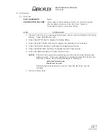
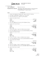
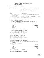
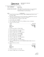
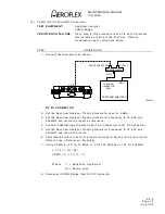
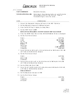
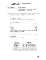
(6) RF Level Flatness (RF I/O Connector)
TEST EQUIPMENT:
Power
Meter
Power
Sensor
VERIFICATION FAILURE:
If any step in this procedure fails or is out of tolerance,
this indicates a failure in the Test Set. Refer to
Troubleshooting for corrective action.
STEP PROCEDURE
1. Connect the Power Sensor to the Power Meter (POWER REF Connector) and
zero Power Meter.
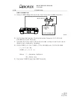
2. Disconnect the Power Sensor from the Power Meter (POWER REF Connector)
and connect the Power Sensor to the RF I/O Connector.
3. Press the SETUP Key to display the Setup Menu.
4. Set the PORT Field to
RF I/O
.
5. Press the MODE Select Key until the VOR Mode Screen is displayed.
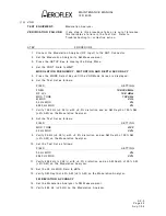
6. Set the Test Set as follows:
FIELD
SETTING
FREQ
108.000 MHz
RF LVL
-20.0 dBm
MOD TONE
OFF
M MOD
0%
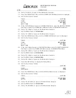
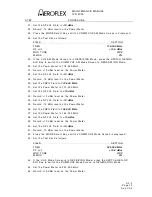
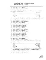
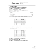
7. Set the Power Meter to 108.000 MHz.
8. Record -20 dBm level on the Power Meter.
9. Set the RF LVL Field to
-40 dBm
.
10. Record -40 dBm level on the Power Meter.
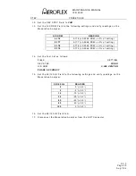
11. Set the FREQ Field to
110.150 MHz
.
12. Set the Power Meter to 110.150 MHz.
13. Set the RF LVL Field to
-20 dBm
.
14. Record -20 dBm level on the Power Meter.
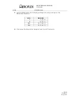
15. Set the RF LVL Field to
-40 dBm
.
16. Record -40 dBm level on the Power Meter.
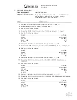
17. Press the MODE Select Key until the MARKER BEACON Mode Screen is
displayed.
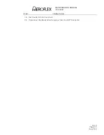
18. Set the Test Set as follows:
FIELD
SETTING
FREQ
75.000 MHz
RF LVL
-20.0 dBm
MOD TONE
OFF
M MOD
0%
19. Set the Power Meter to 75.000 MHz.
20. Record -20 dBm level on the Power Meter.
Содержание IFR 4000
Страница 1: ...NAV COMM Test Set Maintenance Manual 1002 5600 4P0 IFR 4000...
Страница 3: ...MAINTENANCE MANUAL IFR 4000 FOR QUALIFIED SERVICE PERSONNEL ONLY...
Страница 4: ...MAINTENANCE MANUAL IFR 4000 THIS PAGE INTENTIONALLY LEFT BLANK...
Страница 6: ...MAINTENANCE MANUAL IFR 4000 THIS PAGE INTENTIONALLY LEFT BLANK...
Страница 10: ...MAINTENANCE MANUAL IFR 4000 TABLE OF CONTENTS Page 2 Aug 1 04 THIS PAGE INTENTIONALLY LEFT BLANK...
Страница 12: ...MAINTENANCE MANUAL IFR 4000 INTRODUCTION Page 2 Aug 1 04 THIS PAGE INTENTIONALLY LEFT BLANK...
Страница 16: ...MAINTENANCE MANUAL IFR 4000 2 LIST OF ILLUSTRATIONS TABLES Page 2 Aug 1 04 THIS PAGE INTENTIONALLY LEFT BLANK...
Страница 32: ...MAINTENANCE MANUAL IFR 4000 2 2 1 Page 14 Aug 1 04 THIS PAGE INTENTIONALLY LEFT BLANK...
Страница 34: ...MAINTENANCE MANUAL IFR 4000 2 2 1 Page 16 Aug 1 04 THIS PAGE INTENTIONALLY LEFT BLANK...
Страница 42: ...MAINTENANCE MANUAL IFR 4000 2 2 2 Page 8 Aug 1 04 THIS PAGE INTENTIONALLY LEFT BLANK...
Страница 108: ...MAINTENANCE MANUAL IFR 4000 2 2 4 Page 2 Aug 1 04 THIS PAGE INTENTIONALLY LEFT BLANK...
Страница 143: ...MAINTENANCE MANUAL IFR 4000 2 2 4 Page 37 Aug 1 04 056M 09 Figure 12 LCD Assy 7110 5600 000 A 56A1A2A4...
Страница 160: ...MAINTENANCE MANUAL IFR 4000 2 2 4 Page 54 Aug 1 04 THIS PAGE INTENTIONALLY LEFT BLANK...
Страница 166: ...MAINTENANCE MANUAL IFR 4000 2 3 1 Page 6 Aug 1 04 STEP PROCEDURE 4 Remove the Fuse...
Страница 168: ...MAINTENANCE MANUAL IFR 4000 2 3 1 Page 8 Aug 1 04 STEP PROCEDURE 3 Remove four screws 4 Open the Case Assy...
Страница 174: ...MAINTENANCE MANUAL IFR 4000 2 3 1 Page 14 Aug 1 04 STEP PROCEDURE 3 Remove 11 screws 4 Remove Multi Function PCB Assy...
Страница 186: ...MAINTENANCE MANUAL IFR 4000 APPENDIX B Page 2 Aug 1 04 THIS PAGE INTENTIONALLY LEFT BLANK...
Страница 188: ...MAINTENANCE MANUAL IFR 4000 APPENDIX C Page 2 Aug 1 04 THIS PAGE INTENTIONALLY LEFT BLANK...
Страница 200: ...MAINTENANCE MANUAL IFR 4000 APPENDIX D Page 12 Aug 1 04 THIS PAGE INTENTIONALLY LEFT BLANK...
Страница 206: ...MAINTENANCE MANUAL IFR 4000 APPENDIX E Page 6 Aug 1 04 THIS PAGE INTENTIONALLY LEFT BLANK...