9
STA_STH_ 4804200 _02
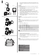
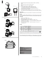
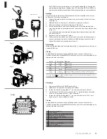
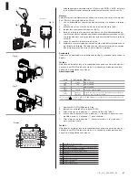
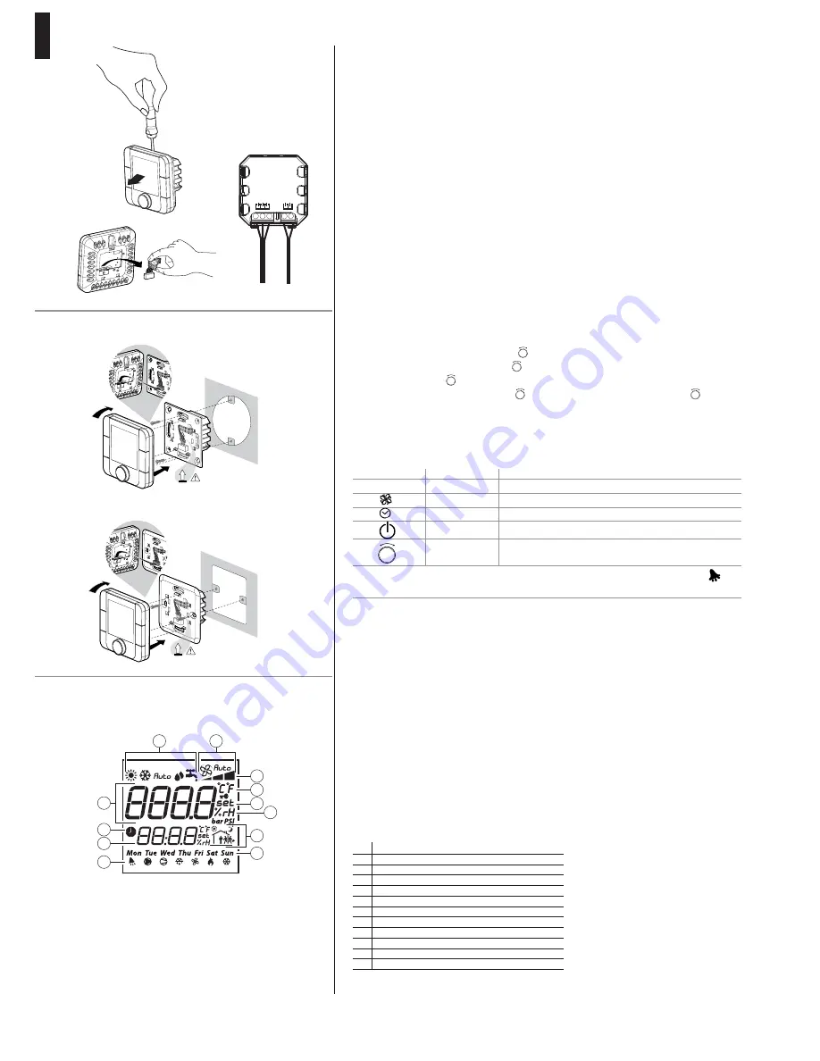
1. separate the front of the terminal from the back using a screwdriver
( fi g.1);
2. disconnect the 5-pin connector from the front
(fi g.2);
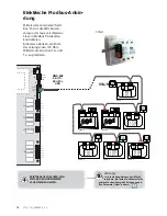
3. make the electrical connections: see (fi g.3);
4. fi x the back to the fl ush box with the two supplied screws:
• for round fl ush models, insert the screws as shown in (fi g.4);
• for rectangular fl ush models, insert the screws as shown in (fi g. 5);
5. insert the 5-pin connector again;
6. fi nally, reinstall the terminal, starting from the lower teeth with a hinge move-
ment. Make sure the electrical wires enter to have the correct snap connection.
Disassembly
Insert a screwdriver into the upper slot (Fig. 1) and press to remove the display
Keypad
The meaning of the buttons and displays can vary depending on the control to
which the STA/STH is connected. A description of the standard settings follows.
Addressing
1. Press FAN and POWER for 5 sec.
2. Enter the password 22, and press PUSCH
3. Turning the adjustment knob
-
+
PUSH
, search the wording “addr”.
4. Having found “addr”, press
-
+
PUSH
and enter the address comprised between
1 and 5, press
-
+
PUSH
to confi rm
5. Turning the adjustment knob
-
+
PUSH
, search the wording “esc”, press
-
+
PUSH
, to
confi rm and exit.
Keypad
The meaning of the buttons and displays can vary depending on the control to
which the STA/STH is connected. A description of the standard settings follows.
Key
Description
Pre-heating
mode
MODE
NOT USED
FAN
NOT USED
NOT USED
POWER
ZONE On/Off
Knob
Adjust.
allows you to change the setpoint. Turn the knob to set the
value and press to confi rm
Access to special menus: MODE + CLOCK for 3s to access the alarms menu, active only if the
icon is on.
-
+
PUSH
Fig.1
Fig.2
Fig.3
Fig.4
connections
Esploso AT******C*
click
4
5
6
click
4
5
6
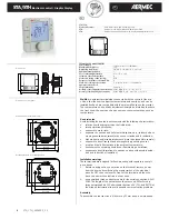
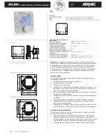
Display
1
3
4
5
6
8
9
10
12
11
7
2
1
Operating mode
2
Main fi eld
3
Fan speed in manual/automatic mode
4
Fan speed indication
5
Temperature reading unit
6
Set point
7
Relative humidity
8
Current time slot
9
Day of the week
10
Actuator on
11
Secondary fi eld
12
Time slots on
Fig.5
230 Vac
GND
Rx+/T
x+
Rx
–/T
x
–
N 230V~
L 50/60H
z
Содержание STA
Страница 2: ......


