18
S300S-S400S-S500S 10.01
5890940_03
By Aermec
• HYDRAULIC CONNECTION
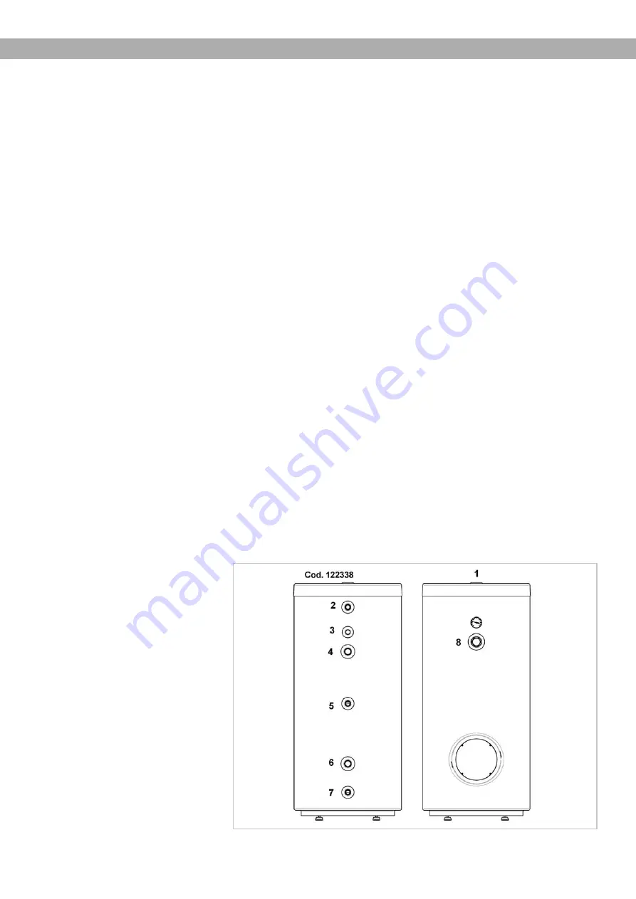
For the position of the connections and
their function (see the specifications of
each storage tank) or the ones indicated
on the label applied at the back of each
storage tank.
Install the appliance near to the grea-
test drawing point of hot water in order
to avoid heat dispersion along the pipes
and possibly near to a drain to facilitate
any emptying operations.
- The cold water feeding duct must
have a safety valve mounted upstre-
am of the heat exchanger.
- The connection duct between the
heat exchanger and the safety valve
must not be intercepted because it
could damage the heat exchanger
as a result of overpressure.
Pay careful attention during the installa-
tion phase of the safety valve (Fig.2-pos.
A). Avoid forcing it at the end run and
tampering with it. The safety valve has
a nominal setting value of 8 bar. Slight
dripping from the safety valve is normal
during the heating phase; for this rea-
son, it should be connected to a siphon
drain.
In the case of a pressure network near
to the valve settings values, an adequate
pressure reducer must be applied (Fig.2-
pos. E), as far away as possible from the
appliance.
In the case that the system is equipped
with a pressure reducer, for the reasons
listed above, and/or a stop valve, an
expansion tank
must be installed
(Fig.2-
pos. D) with a capacity no less than 5%
of the nominal capacity for each heating
appliance.
No stop valve is necessary between the
expansion tank and the safety valve. In
general, the installation of an expansion
tank with the characteristics listed above
is advised in each case, to protect the
appliance and the network.
Inflate the appropriate membrane cham-
ber of the expansion tank according to
instructions from the manufacturer.
Before connecting the appliance to the
network, fill it completely with water as
follows:
• Open the cold water feeding cock;
• Open a hot water tap (e.g. bathroom,
sink etc.) in order to allow the dischar-
ge of air and wait for a constant flow of
water from all the hot water taps.
• Make sure there are not losses along
the various hydraulic connections.
In the presence of hard water with a
value of >20°TH (where 1°TH=French
degree=10mg CaCo3/l), install speci-
fic products that prevent excessive lime
scale precipitation.
Some devices are comparable to the one
way valve and therefore, to use them, an
adequate expansion tank must be instal-
led (see fig. 2).
The appliance is prearranged for con-
nection to a recirculation pipeline (Z): if
mounted, this conduct must be insulated.
For the functioning of recirculation (Z),
install a pump equipped with a timer fun-
ction or a minute counter thermostat, in
order to activate the cooling of the recir-
culation water.
To ensure the availability of hot water
when opening the taps, it is possible to
install a recirculation duct between the
feeding points and the recirculation tube
of the storage tank. This duct must be
provided with a one way valve.
In the case that the connection is not used,
provide with a seal plug. The inlet and out-
let ducts must be connected to the points
pre-determined by the heat exchanger.
Legend
1. Magnesium anode
2. Hot water
3. Tube for sensor
4. Heat exchanger inlet
5. Recirculation
6. Heat exchanger outlet
7. Cold water
8. Attachment for Rp 1” ½ resistance
• Label


