background image

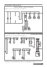
Gli schemi elettrici sono soggetti ad aggiornamento; è opportuno fare riferimento allo schema elettrico allegato all'apparecchio.

Wiring diagrams are subject to modification. Therefore, always refer to the wiring diagram inside the unit.

LEGENDA PER SCHEMI ELETTRICI • 

WIRING DIAGRAMS KEY

AE

= Allarme esterno

Remote alarm

AP

= Pressostato di alta pressione

High pressure switch

BP

= Pressostato di bassa pressione

Low pressure switch

CCP

= Contattore compressore

Compressor contact maker

CM

= Condensatore elettrico

Electric capacitor

CP

= Compressore

Compressor

CPO

= Contattore pompa

Pump contactor

CRE

= Contattore resistenza

Electric heater contactor

CV

= Contattore motori ventilatori

Fan motor contact maker

DCP

= Dispositivo basse temperature

Low ambient temperature device

FL

= Flussostato

Recuperator flow switch

FLR

= Flussostato recupero

Flow switch

FRC

= Filtro antidisturbo

Anti-noise filter

IAD

= Interruttore acceso - spento a distanza

Remote on-off switch

IF

= Interruttore finecorsa

Limit switch

IG

= Interruttore generale

Main switch

IL

= Interruttore di linea

Line switch

L

= Fase di alimentazione

Power supply phase

M

= Morsettiera

Terminal

MPO

= Elettropompa

Motor pump

MTA

= Magnetotermico circuito ausiliario

Auxiliary circuit magneto-thermal cut-out

MTCP = Magnetotermico compressore

Compressor magneto-thermal cut-out

MTPO = Magnetotermico pompa

Pump safety device

MTV

= Magnetotermico motore ventilatore

Fan motor magneto-thermal cut-out

MV

= Motore ventilatore

Fan motor

N

= Neutro di alimentazione

Neutral power

PE

= Collegamento di terra

Earth connection

PR

= Pannello comandi

Control panel

PRC

= Resistenza olio compressore

Compressor oil heater

RCS

= Relè controllo sequenza e tensione

Phase sequence relay

RE

= Resistenza scambiatore

Exchanger heater

SAC

= Sonda accumulo

probe

SAE

= Sonda temperatura aria esterna

Ambient air temperature probe

SC

= Scheda a microprocessore

Microprocessor board

SE

= Scheda espansione

Expansion card

SET

= Secondo set

Second set

SEV

= Sonda evaporatore

Evaporator probe

SIW

= Sonda ingresso acqua

Water inlet probe

SUW

= Sonda uscita acqua

Water outlet probe

SFC

= Sonda free-cooling

free-cooling probe

TAP

= Trasduttore alta pressione

High pressure transducer

TBP

= Trasduttore bassa pressione

Low pressure transducer

TC

= Protezione interna compressore

Compressor internal protection

TGP

= Termostato gas premente

Discharge pipe thermostat

TR

= Trasformatore

Transformer

TSRE

= Termostato sicurezza RE

RE safety thermostat

TV

= Termico ventilatore

Fan thermal protection

VA

= Elettrovalvola premente

Discharge gas solenoid valve

VB

= Elettrovalvola batteria

Coil solenoid valve

VR

= Valvola recupero

Recovery valve

V3V

= Valvola a 3 vie

Three way valve

VRT

= Valvola recupero totale

Total recovery valve

VSL

= Valvola intercettazione liquido

Liquid shut-off valve

Collegamenti da eseguire in loco

On-site wiring

Componenti non forniti

Components not supplied

Accessori

Accessories

52

Aermec S.p.A.

Содержание NRA F 275

Страница 1: ...frigeratori aria acqua Air to water chillers NRA free cooling R407C M M M M A A A A N N N N U U U U A A A A L L L L E E E E T T T T E E E E C C C C N N N N I I I I C C C C O O O O T T T T E E E E C C C C H H H H N N N N I I I I C C C C A A A A L L L L B B B B O O O O O O O O K K K K L L L L E E E E T T T T ...

Страница 2: ...2 Aermec S p A ...

Страница 3: ...ith free cooling 32 DATI SONORI SOUND DATA 33 TAV 13 Pressione e potenza sonora modalità refrigeratore Sound pressure and power level chiller mode 33 TAV 14 Pressione e potenza sonora modalità free cooling Sound pressure and power level free cooling mode 34 TAV 15 PARZIALIZZAZIONI CAPACITY CONTROL 34 TARATURA DISPOSITIVI DI PROTEZIONE PROTECTION DEVICE ADJUSTMENT 35 TAV 16 Campo di taratura dei pa...

Страница 4: ... norme UNI 1285 68 Calcolo di resistenza dei tubi metallici soggetti a pressione interna 3 progettato prodotto e commercializzato in conformità alle seguenti direttive comunitarie Direttiva macchine 98 37 CE Direttiva bassa tensione 73 23 CEE Direttiva compatibilità elettromagnetica EMC 89 336 CEE DECLARATION OF CONFORMITY We declare under our own responsability that the above equipment described ...

Страница 5: ...lità per qualsiasi danno dovuto ad un uso improprio della macchina ad una lettura parziale o superficiale delle informazioni contenute in questo manuale Il numero di pagine di questo manuale è 72 This is one of a set of three manuals that describe this machine The chapters in the table below are present only if relevant to the specific manual Technical Installation User General information x x x M...

Страница 6: ...pianto i compressori funzionano in integrazione del free cooling Tale integrazione sarà tanto minore quanto maggiore sarà il recupero di potenza con free cooling SOLO COMPRESSORI quando la temperatura dell aria esterna è maggiore della temperatura di ritorno dell acqua dall impianto NRA F series units are water chillers equipped with a system to recover the cooling capacity of the outside air know...

Страница 7: ...ia stato preventivamente riscaldato tramite alimentazione delle apposite resistenze elettriche per un periodo di almeno 8 ore La resistenza carter viene alimentata automaticamente alla sosta dell unità purchè l unità venga mantenuta sotto ten sione VERSIONS STANDARD this is the most economic configuration which is obtained by calibrating the finned heat exchanger banks to allow proper operation of...

Страница 8: ...netotermici gruppo d accumulo ad alta prevalenza L unità rispondente alle suddette caratteristiche tecniche è identificata dalla seguente sigla commerciale NRA 650 L F3 UNIT SELECTION NRA series chillers are available in 9 sizes by combining the various options available it is possible to set up each model in the series to meet the widest possible range of system requirements Configuration rules T...

Страница 9: ...275 300 325 350 500 550 600 650 700 Field 7 Field of application standard equipment Y low water temperature up to 10 C Field 8 Model Cooling only Field 9 Heat recover Without recovery Field 10 Version Standard L Low noise A High temperature Field 11 Coils Finned aluminium coils R Finned copper coils S Finned tinned copper coils Field 12 Evaporator To PED standard G To TÜV D standard Germany P To U...

Страница 10: ... swich 6 Tastiera di comando Control keypad 7 Quadro elettrico Electric panel 8 Struttura portante Frame 9 Gruppo ventilante Fan assembly 10 Compressore Compressor 14 Pannello comandi remoto Remote control panel 15 Valvola 3 vie 3 way valve COMPONENTI PRINCIPALI NRA F0 MAIN COMPONENTS NRA F0 NRA Free Cooling senza accumulo NRA Free Cooling without storage tank A L A R M 14 10 Aermec S p A ...

Страница 11: ...colazione Circulation pump 8 Vaso di espansione Expansion Vessel 9 Tastiera di comando Control keypad 10 Quadro elettrico Electric panel 11 Struttura portante Frame 12 Gruppo ventilante Fan assembly 13 Compressore Compressor 14 Pannello comandi remoto Remote control panel 15 Valvola 3 vie 3 way valve COMPONENTI PRINCIPALI NRA F3 F4 MAIN COMPONENTS F3 F4 NRA Free Cooling con accumulo NRA Free Cooli...

Страница 12: ...IERA DI COMANDO Consente il controllo completo dell apparecchio Per una più dettagliata descrizione si faccia riferimento al manuale d uso PANNELLO COMANDO A DISTANZA Consente di eseguire a distanza le operazioni di comando del refrigeratore DESCRIPTION OF COMPONENTS COMPONENTS OF REFRIGERANT CIRCUIT COMPRESSOR Hermetic scroll type compressors fitted with electric heater as standard accessory The ...

Страница 13: ...ella scheda a micro processore il valore della pressione di aspirazione del com pressore uno per circuito Posto sul lato a bassa pressione del circuito frigorifero arresta il funzionamento del com pressore in caso di pressioni anomale di lavoro HYDRAULIC COMPONENTS AIR WATER HEAT EXCHANGER FREE COOLING Crossed by water for free cooling operation It is made with copper tubes and aluminium fins lock...

Страница 14: ...carico ventilatori sovraccarico pompe visualizzazione dei seguenti parametri temperatura ingresso acqua temperatura ingresso acqua evaporatore temperatura uscita acqua delta T alta pressione bassa pressione tempo attesa di riavvio visualizzazione allarmi HIGH PRESSURE SWITCH Variable setting located on the high pressure side of the cooling circuit the switch shuts compressor operation in the event...

Страница 15: ...to di un allarme mediante l accensione di un led rosso sia sul pan nello a bordo macchina sia sul pannello comandi remoto È inoltre a disposizione sulla scheda un contatto pulito in deviazione che viene attivato in caso d allarme morsettiera M1 V 250V Imax 1 A Il microprocessore memorizza in modo permanente gli allar a without password set cooling total differential b with password set anti freeze...

Страница 16: ...e Overwatching Modem Enabling Operation permette il controllo remoto del chiller da un comune telefono cellulare dotato di browser WAP permette inoltre l invio di SMS di allarme o preallarme fino a 3 cellulari GSM anche se non dotati di browser WAP Nel kit viene incluso l AER485 cancel the latter when the power supply has been resto red the unit will not restart and an alarm will be indicated If t...

Страница 17: ...ponibili Available accessories Mod NRA 500 550 600 650 700 AER 485 ROMEO GP 2 x 2 x 2 x 3 x 3 x 3 PGS VT 10 VT 11 VT 13 VT 14 NRA F L Accessori disponibili Available accessories Mod NRA L 275L 300L 325L 350L 500L 550L 600L 650L 700L AER 485 ROMEO GP 2 x 2 x 2 x 3 x 3 x 3 GP 4 PGS VT 10 VT 11 VT 13 VT 14 NRA F A Accessori disponibili Available accessories Mod NRA 275A 300A 325A 350A 500A 550A 600A ...

Страница 18: ... 53 60 71 2 93 4 33 4 33 4 33 L 39 46 53 60 71 2 93 4 33 4 33 4 33 33 6 34 6 29 8 35 7 37 4 E E R W W A 49 5 60 7 64 5 61 6 32 8 33 8 29 3 35 1 37 2 L 47 7 58 9 62 6 59 4 31 7 32 8 28 4 34 4 36 0 14 960 16 340 19 950 22 700 25 460 Portata acqua Water flow rate l h A 9 290 10 660 12 210 14 100 15 650 17 030 20 640 23 390 27 520 L 8 600 9 976 11 350 12 730 14 100 15 480 19 260 22 020 24 770 Perdite ...

Страница 19: ...6 6 8 8 2 2 3 3 3 870 870 870 870 870 Velocità motori ventilatori Fan motor speed g m rpm A 870 870 870 870 870 870 870 870 870 L 870 870 870 870 460 520 690 690 690 Compressori Compressors n scroll scroll scroll scroll scroll scroll scroll scroll scroll Numero compressori circuiti n 2 2 2 2 2 2 2 2 3 2 3 2 4 2 4 2 4 2 Number of compressors circuit Resistenza carter compressori n x W 2 x 75 2 x 75...

Страница 20: ...letta nelle curve in TAV 4 risulta p 92 kPa Sia il valore di Q che quallo di p vanno corretti dai coeffi cienti correttivi di Tav 9 per tener conto della presenza di glicole Q Q x FcGQF 22 188 x 1 13 25 072 l h p p x FcGDpF 92 x 1 65 151 8 kPa To help with selecting a unit here we provide a set of graphs charts and tables that may briefly be described as follows TAB 1 2 3 give the corrective coeff...

Страница 21: ...0 ad ogni grado in più di differenza tra temperatura aria esterna e tem peratura acqua di ritorno dall impianto mentre l efficienza della macchina solo compressori rimarrà sostanzialmente invariata circa 4 di COP We now need to apply the correction factor of the mean temperature at the evaporator Performance in winter conditions Since the outside air temperature is much lower than the temperature ...

Страница 22: ...ITS Units in the standard configuration are not suited for instal lation in seaside locations The minimum and maximum limits for water flow to the exchanger are indicated by the curves in the load loss diagrams For operating limits refer to the diagrams below Temp aria esterna b s C Outdoor air temp d b C DATI DI PROGETTO DESIGN DATA R407C Lato in alta pressione Lato bassa pressione High pressure ...

Страница 23: ...ted ones are found by multi plying the rated values Pf Pa indicated in the table by the respective correction coefficients Cf Ca The following diagrams make it possible to calculate the cor rection coefficients to be used for the various versions of each appliance when used for cooling the external air temperatu re referred to is indicated in correspondence with each curve Campo di lavoro con glic...

Страница 24: ...rective coefficient Pa TAV 2 VERSIONE SILENZIATA PER LE GRANDEZZE 500 550 600 650 700 LOW NOISE VERSIONS FOR SIZE 500 550 600 650 700 Per t diversi da 5 C all evaporatore si utilizzi la Tav 10 per ottenere i fattori correttivi della potenza frigorifera ed assor bita Per tenere conto dello sporcamento degli scambiatori si utilizzano i relativi fattori di sporcamento For t different from 5 C refer t...

Страница 25: ...ua prodotta e della temperatura dell aria esterna Tali valori sono riferiti a ventilatori a pieni giri massima poten za assorbita se la potenza resa dovesse risultare in eccesso interverrà una modulazione sul numero di giri Coefficente correttivo della potenza frigorifera free cooling Pf free cooling capacity corrective factor Pf Temperatura dell aria esterna C External air temperature C The maxim...

Страница 26: ...325 350 D 500 E 550 600 F 650 G 700 Le perdite di carico dei diagrammi precedenti sono relative ad una temperatura media dell acqua di 10 C La tabella seguente riporta la correzione da applicare alle perdite di carico al variare della temperatura media dell acqua The pressure drops in the charts above refer to an average water temperature of 10 C The following table shows the corrections to apply ...

Страница 27: ...ty correction factor FCTPA Fattore di correzione potenza assorbita Input power correction factor TAV 7 TABELLE DI CORREZIONE CORRECTION TABLES Fattore di sporcamento Fouling factor K m2 W 0 00005 0 0001 0 0002 FCSPF 1 0 98 0 94 FCSPA 1 0 98 0 95 FCSPF Fattore di correzione potenza frigorifera Cooling capacity correction factor FCSPA Fattore di correzione potenza assorbita Input power correction fa...

Страница 28: ...rrezione di portata acqua e perdite di carico vanno applicati direttamente ai dati ricavati per funzionamento senza glicole The water flow rate and pressure drop correction factors are to be applied directly to the values given for operation without glycol 0 96 0 97 0 98 0 99 1 00 0 5 10 15 20 25 30 35 FcGPf FcGPa TAV 8 CORREZIONE POTENZA PER FUNZIONAMENTO CON ACQUA GLICOLATA POWER CORRECTION FOR ...

Страница 29: ...sup plied with plastic plugs for provisional sealing of the holes Before starting installation fit the electric resistors Should the resistors not be required immediately the plastic plugs must be replaced with suitable metal plugs NRA F3 F4 Vers 275 300 325 350 500 550 600 650 700 Capacità sebatoio tutte all l 300 300 300 300 300 300 300 300 300 Tank capacity Resistenza el antigelo tutte all W 30...

Страница 30: ...batoio d accumulo è superiore a quello riportato in tabella alle condizioni operative dovrà essere installato un ulteriore vaso d espansione aggiuntivo dimen sionato utilizzando i criteri abituali con riferimento al volu me d acqua aggiuntivo Nelle tabelle seguenti si possono ricavare i valori di massi mo contenuto dell impianto anche per altre condizioni di funzionamento con acqua glicolata I val...

Страница 31: ...he tank must be calibrated according to the maximum dif ference in level H with respect to the user see figure applying the formula p calibration bar H m 10 2 0 3 For example if the difference in level H is 20 m the tank calibration value will be 2 3 bar If the calibration value obtained is lower than 1 5 bar that is to say H 12 25 the standard calibration should be maintained TARATURA DEL VASO D ...

Страница 32: ...00 E 550 F 600 G 650 H 700 Le prestazioni sono riferite alle seguenti condizioni temperatura acqua prodotta 7 C Performances refer to following conditions temperature of processed water 7 C A 275 B 300 C 325 350 D 500 E 550 F 600 G 650 H 700 Le portate d acqua per ogni taglia di macchina devono esse re comprese tra i seguenti valori minimi e massimi 0 5xQn Q 1 67xQn dove Qn è la portata nominale T...

Страница 33: ...79 7 74 0 NRA F 550 54 5 84 1 78 4 77 9 77 6 76 5 71 2 62 3 87 0 82 5 NRA F 550 A 54 5 84 1 78 4 77 9 77 6 76 5 71 2 62 3 87 0 82 5 NRA F 550 L 46 5 78 9 73 1 70 7 69 4 67 1 62 6 54 0 81 0 74 5 NRA F 600 55 0 85 6 78 8 78 4 78 0 77 0 72 1 63 0 88 1 83 0 NRA F 600 A 55 0 85 6 78 8 78 4 78 0 77 0 72 1 63 0 88 1 83 0 NRA F 600 L 49 0 81 5 79 8 74 3 70 1 68 0 62 1 53 9 84 5 77 0 NRA F 650 56 0 86 7 80...

Страница 34: ...0 52 0 85 0 79 0 74 5 75 5 72 6 68 8 60 1 86 8 80 0 I dati riportati esprimono la potenza sonora totale emessa dalla macchina alle condizioni nominali di funzionamento in raf freddamento Pressione sonora in campo libero a 10 m di distanza con fattore di direzionalità 2 The data given the total sound power level ratings of the unit at nominal operating conditions in cooling sound pressure in free f...

Страница 35: ...i casi di non dover ricorrere ad operazio ni aggiuntive Qualora comunque si intendesse operare con portate d acqua inferiori di oltre il 20 a quelle nominali si dovranno eseguire le seguenti operazioni di taratura 1 avviare l unità e portarla a regime 2 leggere sul display del pannello comandi il valore del dif ferenziale temperatura acqua tra ingresso e uscita 3 chiudere lentamente la valvola man...

Страница 36: ...iltro acqua flussostato gruppo di pompaggio vaso d espansione gruppo di riempimento con manometro valvola di sfiato SUGGESTED EXTERNAL HYDRAULIC CIRCUIT All hydraulic circuits in the NRA F appliances are supplied complete with water filter and flow switch 5 to safeguard the plate heat exchangers WARNING the presence of the filter is to be considered mandatory the guarantee will no longer be valid ...

Страница 37: ... with pressure gauge V Ventilatore Fan VESP Vaso di espansione Expansion tank V3V Valvola 3 vie motorizzata Motorized 3 way valve VSF Separatore d aria con valvola di sfiato automatica Air separator with automatic air vent VSA Valvola scarico acqua Water discharge valve VSIC Valvola di sicurezza Safety valve E V FM SIW Sw inev H2O Sw out V3V V FL V SUW IN OUT Free Cooling FC Free Cooling FC E V FM...

Страница 38: ...t 1 2 Gas M Uscita acqua Water output Femmina Female 2 1 2 Gas N Ingresso acqua Water input Femmina Female 2 1 2 Gas 182 285 D DIMENSIONI E POSIZIONE ATTACCHI DIMENSIONS AND POSITION OF CONNECTIONS mm 1100 395 275 433 548 D N M Mod NRA F0 F3 F4 275 300 325 350 L A 38 Aermec S p A ...

Страница 39: ...IMENSIONI E POSIZIONE ATTACCHI DIMENSIONS AND POSITION OF CONNECTIONS mm D 1100 395 275 433 548 N M D EL 1100 395 275 433 548 N M Mod NRA F 600 650 700 A L Mod NRA F 500 550 A L NRA Fc Cod 6871970_00 39 ...

Страница 40: ...a acqua aria Water to air heat exchanger FD Filtro deidratatore Dehumidifier filter IDL Indicatore di liquido Sight glass MPO Pompa acqua Water pump TP1 Trasduttore di bassa pressione Low pressure transducer TP2 Trasduttore di alta pressione High pressure transducer V Ventilatore Fan VS Valvola solenoide Solenoid valve VSIC Valvola di sicurezza Safety valve VT Valvola termostatica Thermostatic val...

Страница 41: ...le a destra e a sinistra electric power inlet available on right and left sides DIMENSIONI DIMENSIONS mm Mod NRA F0 F3 F4 275 300 325 350 L A L 1875 140 215 125 EL 1100 Mod NRA F0 L 500 550 A L 2950 Mod NRA F3 F4 con accumulo with storage tank L 500 550 A L 3200 DATI DIMENSIONALI DIMENSIONS NRA Fc Cod 6871970_00 41 ...

Страница 42: ...DIMENSIONI DIMENSIONS mm 3950 1875 140 215 125 D EL 1100 N M Mod NRA F0 F3 F4 600 650 700 A L 32 130 76 PANNELLO DI COMANDO A DISTANZA REMOTE CONTROL PANEL 42 Aermec S p A ...

Страница 43: ...030 1 245 1 295 1 545 1 660 1 710 Gx mm 1 090 1 125 1 100 1 075 1 325 1 325 1 695 1 700 1 665 Gy mm 550 550 550 550 565 560 550 550 550 A 32 32 32 32 26 27 28 28 29 B 32 32 32 32 28 27 28 28 29 C 18 18 18 18 22 23 22 22 21 D 18 18 18 18 24 23 22 22 21 CON ACCUMULO VUOTO WITH EMPTY STORAGE TANK Grandezza Size 275 300 325 350 500 550 600 650 700 Peso Weight kg 975 1 095 1 110 1 150 1 385 1 435 1 665...

Страница 44: ... 155 1 170 1 210 1 385 1 435 1 665 1 780 1 830 Gx mm 1 183 1 205 1 182 1 158 1 393 1 391 1 706 1 710 1 677 Gy mm 550 550 550 550 565 560 550 550 550 CON ACCUMULO PIENO D ACQUA 300 litri WITH FULL STORAGE TANK 300 litres Grandezza Size 275 300 325 350 500 550 600 650 700 Peso Weight kg 1 375 1 505 1 520 1 560 1 760 1 810 2 040 2 165 2 215 Gx mm 1 274 1 285 1 267 1 246 1 523 1 517 1 733 1 735 1 707 ...

Страница 45: ...aricentro Center of gravity BARICENTRO E PUNTI DI APPOGGIO CENTER OF GRAVITY AND SUPPORTS Mod NRA F0 F3 F4 500 550 A L Mod NRA F0 F3 F4 275 300 325 350 L A Le dimensioni sono riferite al basamento delle unità Dimensions refer to the basement Mod NRA F0 F3 F4 600 650 700 A L NRA Fc Cod 6871970_00 45 ...

Страница 46: ...Mod NRA 275 A L NRA 300 A L NRA 325 A L NRA 350 A L NRA 500 A L NRA 550 A L NRA 600 A L NRA 650 A L NRA 700 A L Mod NRA 600 A L NRA 650 A L NRA 700 A L A B øC n A B C VT 10 4 155 95 M14 Nero Black VT 11 6 155 95 M14 Nero Black VT 13 4 135 81 M14 Nero Black VT 14 2 135 81 M14 Nero Black 2 155 95 M14 Nero Black Nei modelli con accumulo In models with storage tank 46 Aermec S p A ...

Страница 47: ...check its dimensions weight centre of gravity and lifting points then make sure that the lifting and positioning equipment to be used is adequate and that it complies with current safety regulations Particular care must be taken during all loading unloading and lifting operations to avoid potential danger to persons damage to carpentry works and damage to the machine s working parts Never place ob...

Страница 48: ...a macchina in zone partico larmente ventose occorre prevedere delle barriere frangi vento per evitare un funzionamento instabile del dispositivo DCPX POSITIONING Le macchine della serie NRA devono essere installate all e sterno in zona adeguata Pertanto dovrà essere installata prevedendo gli spazi tecnici necessari vedi Dati dimensio nali Questo è indispensabile sia per consentire gli inter venti ...

Страница 49: ...in funzione gratuita da parte del Servizio Assistenza AERMEC di zona La messa in funzione dev essere preventivamente concorda ta in base ai tempi di realizzazione dell impianto Prima dell intervento del Servizio Assistenza AERMEC tutte le opere allacciamenti elettrici e idraulici caricamento e sfiato dell aria dall impianto dovranno essere state ultimate Per l impostazione di tutti i parametri fun...

Страница 50: ...dine IMPROPER USES The unit is designed and constructed to guarantee maximum safety in its immediate proximity and to resist weathering The fans are shielded against accidental contact by a protec tive guard Accidental opening of the electric switchboard with the machine in operation is impeded by the safety door interlock Tools or heavy objects must not be leaned directly against the lateral exch...

Страница 51: ... installation technician is responsible for dimensioning the power line as appropriate in relation to its length the cable type unit absorption and position All electrical connections should comply with standing regu lations at the time of machine installation The diagrams in this document should only be used as a guide when making electrical connections For particular installation requirements re...

Страница 52: ...fety device MTV Magnetotermico motore ventilatore Fan motor magneto thermal cut out MV Motore ventilatore Fan motor N Neutro di alimentazione Neutral power PE Collegamento di terra Earth connection PR Pannello comandi Control panel PRC Resistenza olio compressore Compressor oil heater RCS Relè controllo sequenza e tensione Phase sequence relay RE Resistenza scambiatore Exchanger heater SAC Sonda a...

Страница 53: ... 4 VB1 5 VSL1 6 F 1A 250V F 1A 250V TAP2 SEV1 TBP2 6 5 SEV2 AE TAP1 SFC SAE TBP1 SUW SIW SCHEDA ELETTRONICA ELECTRONIC BOARD CARTE ELECTRONIQUE ELEKTRONISCHE STEUERPLATINE NRA 275 300 325 350 500 550 600 700 M1 INGRESSO PROTEZIONI M2 RS 485 M3 VISUALIZZATORE M4 REG VEL VENTIL M5 LIBERA M6 ALIMENTAZ SIC 24V M7 COMANDO REMOTO M8 SICUREZZE COMUNI M9 INGRESSO PROTEZIONI M10 INGRESSO PROTEZIONI M11 ING...

Страница 54: ... 7 5 3 1 8 6 4 2 L3 L2 L1 N 1 2 3 4 5 6 1 2 U V PE W 3 4 5 6 1 2 3 4 5 6 1 2 U V PE W 3 4 5 6 1 2 3 4 2 4 6 8 1 2 3 4 2 0 COLLEGAMENTO ALIMENTAZIONE POWER CONNECTIONS NRA 275 300 M 3 M 3 DCP1 5 1 RCS 3 3 5 1 4A 2 0 L3 L2 L1 N PE LINEA 400V 50Hz 3Ph N SEZ A COMPRESSORE 1 COMPRESSORE 2 N N M 1 L LOAD V M 1 VENTILATORE M 1 DCP 1 2 M 1 3 N N M 1 L LOAD V M 1 VENTILATORE M 1 DCP CIRCUITO AUSILIARIO 230...

Страница 55: ...0 24 230 0 24 CIRCUITO AUSILIARIO AUXILIARY CONNECTIONS M16 SC 2 50 18 1 51 19 M14 SC M1 SE1 6 52 1 21 2 1 23 4 1 25 6 2 121 22 6 88 5 53 5 89 40 4 54 1 42 4 1 46 8 4 90 3 3 91 40 2 2 92 ANTIGELO EVAPORATORE 1 93 1 M15 SC M2 SE1 6 58 1 31 2 1 33 4 1 35 6 2 121 22 6 94 5 5 95 40 4 4 96 3 3 97 40 2 2 1 98 1 99 4 611 12 4 614 230V 2 61 15 MA 2 M 1 24V 11 62 16 NE 1 2 4 0V 10 17 BL 3 M2 SE2 M1 SE2 6 6...

Страница 56: ...9 96 2 15 10 97 3 16 P 4 17 M9 SC M10 SC 1 18 1 23 24 11 80 2 19 2 25 12 81 3 3 4 4 5 29 6 30 M11 SC 1 31 P 2 32 M12 SC 1 35 36 13 84 3 4 2 37 14 85 5 3 6 4 M1 SC 5 1 6 2 3 4 PR 0 1 M7 SC 6 x 0 5 MAX 50m 7 6 6 5 5 4 4 3 3 2 2 1 1 IAD ALARM FL AP1 MTV 1 4 MTCP1 1 2 TC1 TGP1 RCS 1 5 AP2 MTCP2 1 3 TC2 SET TGP2 FLR 33 34 13 14 6 8 13 14 COLLEGAMENTO SICUREZZE COMANDO A DISTANZA SAFETY CONNECTIONS REMO...

Страница 57: ...02 60 5 100 60 4 103 4 101 3 104 60 3 2 105 60 2 1 106 1 CPO CCP1 VSL1 VB1 CV VA1 CCP1A TSRE RE CCP2 VSL2 VB2 VA2 CCP2A R1 R1 4 5 V3V 2 4 VA2 VA1 VA2 VB1 A1 A2 A1 A2 M1 SE1 A1 A2 A1 A2 MAX 650W A1 A2 M2 SE1 A1 A2 A1 A2 2 9 14 11 12 COLLEGAMENTO CARICHI LOAD CONNECTIONS NRA 500 550 M 3 M 3 M 3 U M 3 V W DCP M 3 5 1 4A L3 L2 L1 N PE LINEA 400V 50Hz 3Ph N SEZ A COMPRESSORE 1 COMPRESSORE 1A COMPRESSOR...

Страница 58: ...1 4 1 RC1 CCP1A 4 2 RC1A CCP2 4 3 RC2 FRC TR 21 22 21 22 21 22 L1 L2 0 0 24 230 0 24 CIRCUITO AUSILIARIO AUXILIARY CONNECTIONS NRA 500 550 M8 SC 1 14 11 96 2 15 12 97 3 16 P 4 17 M9 SC M10 SC 1 18 19 24 1 23 24 13 80 2 20 25 2 25 14 81 3 3 26 27 15 82 4 4 28 16 83 5 29 1 31 P 6 30 2 32 3 1 35 36 17 84 4 2 37 18 85 5 6 3 M1 SC 4 1 5 2 6 3 4 PR 0 1 M7 SC 6 x 0 5 MAX 50m 7 6 6 5 5 4 4 3 3 2 2 1 1 IAD...

Страница 59: ...2 105 60 2 1 106 1 CPO CCP1 VSL1 VB1 CV VA1 CCP1A TSRE RE CCP2 VSL2 VB2 VA2 CCP2A R1 R1 4 5 V3V 2 4 VB2 VA1 VA2 VB1 A1 A2 A1 A2 M1 SE1 A1 A2 A1 A2 MAX 650W A1 A2 M2 SE1 A1 A2 A1 A2 2 9 14 11 12 COLLEGAMENTO CARICHI LOAD CONNECTIONS NRA 600 700 M 3 M 3 M 3 M 3 U M 3 V W DCP M 3 5 1 M 3 4A L3 L2 L1 N PE LINEA 400V 50Hz 3Ph N SEZ A COMPRESSORE 1 COMPRESSORE 1A COMPRESSORE 2 COMPRESSORE 2A VENTILATORE...

Страница 60: ... 3 RC2 CCP2A 4 5 RC2A FRC TR 21 22 21 22 21 22 21 22 L1 L2 0 0 24 230 0 24 CIRCUITO AUSILIARIO AUXILIARY CONNECTIONS NRA 600 700 1 14 13 96 2 15 14 97 3 16 P 4 17 M9 SC M10 SC 1 18 19 28 1 23 24 15 80 2 20 29 2 25 16 81 3 3 26 27 17 82 4 4 28 18 83 5 29 1 31 P 6 30 2 32 3 1 35 36 19 84 4 2 37 20 85 5 6 3 38 39 21 86 4 40 22 87 1 5 2 6 3 4 PR 0 1 M7 SC 6 x 0 5 MAX 50m 7 6 6 5 5 4 4 3 3 2 2 1 1 IAD ...

Страница 61: ...EV2 AE TAP1 SFC SAE TBP1 SUW SIW SCHEMI ELETTRICI WIRING DIAGRAMS SCHEDA ELETTRONICA ELECTRONIC BOARD CARTE ELECTRONIQUE ELEKTRONISCHE STEUERPLATINE NRA 275 300 325 350 500 550 600 700 con accumulo with storage tank M1 INGRESSO PROTEZIONI M2 RS 485 M3 VISUALIZZATORE M4 REG VEL VENTIL M5 LIBERA M6 ALIMENTAZ SIC 24V M7 COMANDO REMOTO M8 SICUREZZE COMUNI M9 INGRESSO PROTEZIONI M10 INGRESSO PROTEZIONI...

Страница 62: ...1 A2 MAX 550W A1 A2 A1 A2 2 9 14 11 12 A1 A2 M2 SE2 M1 SE2 COLLEGAMENTO CARICHI LOAD CONNECTIONS M 3 M 3 M 3 M 3 DCP 5 1 4A 2 0 L3 L2 L1 N PE LINEA 400V 50Hz 3Ph N SEZ A COMPRESSORE COMPRESSOR COMPRESSORE COMPRESSOR POMPA PUMP POMPA PUMP N N M 1 L LOAD V M 1 VENTILATORE FAN RCS 3 3 1 2 M 1 DCP 3 M 1 M 1 CIRCUITO AUSILIARIO 230V 50Hz N M 1 L2 IL IG MTCP1 3 2 CCP1 4 1 CP1 MTCP2 3 4 CCP2 4 3 CP2 MTPO...

Страница 63: ...4 L1 L2 0 0 24 230 0 24 CIRCUITO AUSILIARIO AUXILIARY CONNECTIONS 1 14 9 96 2 15 10 97 3 16 P 4 17 M9 SC M10 SC 1 18 1 23 24 11 80 2 19 2 25 12 81 3 3 4 4 5 29 6 30 M11 SC 1 31 P 2 32 M12 SC 1 35 36 13 84 3 4 2 37 14 85 5 3 6 4 M1 SC 5 1 41 6 11 2 42 3 2 4 24V 4 10 2 4 0V PR 0 1 M7 SC 6 x 0 5 MAX 50m 7 6 6 5 5 4 4 3 3 2 2 1 1 IAD ALARM M8 SC FL AP1 MTV 1 6 MTCP1 1 2 TC1 TGP1 RCS 1 7 AP2 MTCP2 1 3 ...

Страница 64: ... MPO1 MTPO2 4 6 CPO2 5 7 MPO2 7 5 3 1 8 6 4 2 L3 L2 L1 N 1 2 3 4 5 6 1 2 U V PE W 3 4 5 6 1 2 3 4 5 6 1 2 U V PE W 3 4 5 6 1 2 3 4 5 6 1 2 U V PE W 3 4 5 6 1 2 3 4 5 6 1 2 U V PE W 3 4 5 6 COLLEGAMENTO CARICHI LOAD CONNECTIONS T S R N N N M 1 L LOAD V M 1 M 1 DCP 1 2 M 1 3 DCP2 N N M 1 L LOAD V M 1 M 1 DCP M 1 CIRCUITO AUSILIARIO 230V 50Hz 4A N 3 0 L2 1 8 1 8 1 8 1 8 DCP1 6 1 RCS 4 3 6 1 MTV 4 2 C...

Страница 65: ...P2 4 4 CCP2 5 3 CP2 MTPO1 4 6 CPO1 5 0 MPO1 MTPO2 4 6 CPO2 5 7 MPO2 7 5 3 1 8 6 4 2 L3 L2 L1 N 1 2 3 4 5 6 1 2 U V PE W 3 4 5 6 1 2 3 4 5 6 1 2 U V PE W 3 4 5 6 1 2 3 4 5 6 1 2 U V PE W 3 4 5 6 1 2 3 4 5 6 1 2 U V PE W 3 4 5 6 1 2 3 4 5 6 1 2 U V PE W 3 4 5 6 COLLEGAMENTO ALIMENTAZIONE POWER CONNECTIONS NRA 500 550 con accumulo with storage tank 1 8 1 8 1 8 1 8 U M 3 V W DCP M 3 RCS 4 4 6 1 L3 L2 ...

Страница 66: ...4 230 0 24 CIRCUITO AUSILIARIO AUXILIARY CONNECTIONS NRA 500 550 con accumulo with storage tank 2 50 1 51 M14 SC 6 52 6 88 5 53 5 89 4 54 4 90 3 3 91 2 56 2 92 ANTIGELO EVAPORATORE ACCUMULO 1 1 93 M15 SC 6 58 6 94 5 59 5 95 4 4 96 3 3 97 2 2 1 1 99 98 230V 2 61 19 MA 2 M 1 24V 11 62 20 NE 1 0V 10 21 BL 3 62 6 6 63 5 102 5 100 4 103 4 101 3 104 3 2 105 2 1 106 1 M16 SC CPO1 CCP1 VSL1 VB1 CV VA1 CCP...

Страница 67: ...9 28 1 23 24 13 80 2 20 29 2 25 14 81 3 3 26 27 15 82 4 4 28 16 83 5 29 1 31 P 6 30 2 32 3 1 35 36 17 84 4 2 37 18 85 5 6 3 M1 SC 4 1 41 5 11 2 42 6 3 24V 4 10 0V PR 0 1 M7 SC 6 x 0 5 MAX 50m 7 6 6 5 5 4 4 3 3 2 2 1 1 IAD ALARM M8 SC FL AP1 MTV TV1 TV2 MTCP1 TC1 TV3 TGP1 MTCP1A TC1A TGP1A RCS AP2 SET MTCP2 TC2 TGP2 MTPO1 FLR MTPO2 33 34 13 14 13 14 6 8 M11 SC M12 SC 13 14 33 34 33 34 NRA 500 550 c...

Страница 68: ...1 CPO1 MPO1 MTPO2 CPO2 MPO2 7 5 3 1 8 6 4 2 L3 L2 L1 N 1 2 3 4 5 6 1 2 U V PE W 3 4 5 6 1 2 3 4 5 6 1 2 U V PE W 3 4 5 6 1 2 3 4 5 6 1 2 U V PE W 3 4 5 6 1 2 3 4 5 6 1 2 U V PE W 3 4 5 6 1 2 3 4 5 6 1 2 U V PE W 3 4 5 6 1 2 3 4 5 6 1 2 U V PE W 3 4 5 6 COLLEGAMENTO ALIMENTAZIONE POWER CONNECTIONS NRA 600 650 700 con accumulo with storage tank 1 8 1 8 1 8 1 8 U M 3 V W DCP M 3 6 1 M 3 L3 L2 L1 N VE...

Страница 69: ...E ACCUMULO 1 1 93 M15 SC 6 58 6 94 5 59 5 95 4 4 96 3 3 97 2 60 2 1 1 99 98 230V 2 61 23 MA 2 M 1 24V 11 62 24 NE 1 0V 10 25 BL 3 64 6 6 63 5 102 5 100 4 103 4 101 3 104 3 2 105 2 1 106 1 40 40 40 40 60 M16 SC CPO1 CCP1 VSL1 VB1 CV VA1 CCP1A TSRE RE CCP2 VSL2 VB2 VA2 CCP2A R1 R1 V3V CPO2 VB2 VA1 VA2 VB1 A1 A2 A1 A2 M1 SE1 A1 A2 A1 A2 MAX 650W A1 A2 M2 SE1 A1 A2 A1 A2 14 11 12 A1 A2 M2 SE2 M1 SE2 6...

Страница 70: ...30 0 24 4 7 4 7 CIRCUITO AUSILIARIO AUXILIARY CONNECTIONS 1 14 13 96 2 15 14 97 3 16 P 4 17 M9 SC M10 SC 1 18 19 26 1 23 24 15 80 2 20 27 2 25 16 81 3 3 26 27 17 82 4 4 28 18 83 5 29 1 31 P 6 30 2 32 3 1 35 36 19 84 4 2 37 20 85 5 6 3 38 39 21 86 4 40 22 87 1 41 5 11 2 42 6 3 24V 4 10 0V PR 0 1 M7 SC 6 x 0 5 MAX 50m 7 6 6 5 5 4 4 3 3 2 2 1 1 IAD ALARM M8 SC FL AP1 MTV TV1 TV2 MTCP1 TC1 TV3 TGP1 MT...

Страница 71: ...4 Finale Emilia MO 053 592 156 MODENA Sud AERSAT s n c di Leggio M Lolli S Piazza Beccadori 19 41057 Spilamberto MO 059 782 908 PARMA ALFATERMICA s n c Galbano Biondo Via Mantova 161 43100 Parma 0521 776 771 PIACENZA MORETTI ALBANO C s n c Via Manini 2 C 26100 Cremona 0372 433 624 REGGIO EMILIA ECOCLIMA S r l Via Maestri del lavoro 14 42100 Reggio Emilia 0522 558 709 TOSCANA AREZZO CLIMA SERVICE E...

Страница 72: ...modifications deemed necessary to the improvement of the product Aermec partecipa al Programma di Certificazione EUROVENT I prodotti interessati figurano nella Guida EUROVENT dei Prodotti Certificati Aermec is partecipating in the EUROVENT Certification Programme Products are as listed in the EUROVENT Directory of Certified Products AERMEC S p A I 37040 Bevilacqua VR Italia Via Roma 44 Tel 39 0442...

Отзывы: