background image

USER MANUAL 


COOLMAX SRX – Wall Mount 

Australian Energy Research Labs 

AER09 – Rev 1.2 

7

th

 July 2022


AER09 REV 1.2 


Thank-you for purchasing an Australian made CoolMax 600 Series Charge Controller.  


CoolMax Charge Controllers offer an efficient and reliable charging process that not only maintains battery 
efficiency and life but maximizes power generation by utilizing the full potential of your PV array. 


Features 


CoolMax Charge Controllers utilize an advanced form of Maximum Power Point Tracking (MPPT) 
technology to extract the maximum power available from your PV array, efficiently charging your batteries 
and maximizing power generation. 


AERL’s Maximum Power Point Tracking (MPPT) algorithm has been proven to be highly robust, resistant to 
local extremes, and results in power losses of less than 0.5% over the whole operating temperature range 
of a PV Array. 


•  High Input Voltage for Ease of Install 

•  On-Board Ground Fault Detection 

•  PV Array Oversizing Support (+33%) 

•  Superior Peak Power Efficiency  

•  Built-In Overload and Thermal Protection  

•  Reverse Polarity and Current Protection 

•  Master/Slave Operational Mode 

•  Designed for Long Term Reliability 

• 

Australian Made


Firmware 


This user manual covers CoolMax SRX Control Firmware Revisions v1.3.1 and above. 


Introduction 


Содержание CoolMax SRX 600/30-120

Страница 1: ...CoolMax SRX Charge Controller Installation and Operation User Manual Models SRX 600 55 48 SRX 600 70 48 SRX 600 30 120...

Страница 2: ...ro Wind and Cathodic Protection applications Contact Information Address 2 75 Bluestone Circuit Seventeen Mile Rocks 4073 Queensland Australia Phone 61 1800 950 865 Email sales aerl com au Website htt...

Страница 3: ...Disconnect Sizing 11 CoolMax 600 55 48 11 CoolMax 600 70 48 11 CoolMax 600 35 120 11 Wiring Compartment 12 Wiring Polarity 13 Operation 14 Powering Up 14 Programming the Device 14 Device Status Indic...

Страница 4: ...er Manual be read before beginning installation Only qualified electricians and technicians should install the COOLMAX SRX This manual is intended for all installation technicians and the system owner...

Страница 5: ...ile Rocks Australia after contacting AERL and receiving the appropriate RMA documentation from AERL No allowance is made for labour or travelling time required to disconnect or reinstall faulty parts...

Страница 6: ...Power Limitation PV Reverse Polarity Protection Yes Yes Yes Earth Leakage Current Detection Yes Yes Yes Safety Protection Class I I I Pollution Degree Internal I I I Pollution Degree External III III...

Страница 7: ...maximum power available from your PV array efficiently charging your batteries and maximizing power generation AERL s Maximum Power Point Tracking MPPT algorithm has been proven to be highly robust re...

Страница 8: ...sunlight Optimal cooling is achieved when the COOLMAX SRX is mounted vertically A minimum of 15cm should be kept clear above the COOLMAX SRX to allow for cooling CoolMax Charge Controllers are not de...

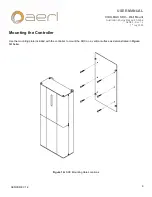
Страница 9: ...rgy Research Labs AER09 Rev 1 2 7th July 2022 9 AER09 REV 1 2 Mounting the Controller Use the mounting plate included with the controller to mount the SRX on a vertical surface as demonstrated in Figu...

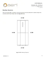
Страница 10: ...2 7th July 2022 10 AER09 REV 1 2 Mounting Clearances When mounting the SRX a clearance zone around the device must be adhered to for optimal cooling of the controller under full load Please refer to...

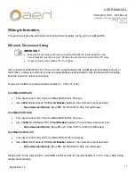
Страница 11: ...oller output and load o Recommended Option Beny BB1 63 63A 600V 2 Pole Circuit Breaker CoolMax 600 70 48 The output current limit of the CoolMax 600 70 48 is 70 amps Use a 125A Non Polarized DC Circui...

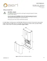
Страница 12: ...r side of the access panel Refer to Figure 2 below Figure 2 SRX Access Panel Screw Locations CAUTION Hazard All CoolMax SRX wiring must enter the unit through the entry ports located in the base and r...

Страница 13: ...al PV Input and Battery Output terminals will be visible Refer to Figure 3 below Figure 3 SRX Access Cover Removed CAUTION Equipment Damage Reversing the polarity of either the input or output may dam...

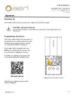
Страница 14: ...on strip will appear yellow to indicate no charge profile has been configured The CoolMax SRX is programmed via the USB C port located inside the access cover as demonstrated in Figure 4 to the right...

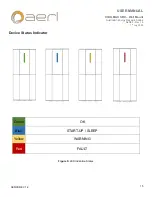
Страница 15: ...L COOLMAX SRX Wall Mount Australian Energy Research Labs AER09 Rev 1 2 7th July 2022 15 AER09 REV 1 2 Device Status Indicator Green OK Blue START UP SLEEP Yellow WARNING Red FAULT Figure 5 LED Indicat...

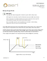
Страница 16: ...r optimal battery life and performance These voltages can be adjusted in the charge profile settings Refer to Page 18 for instructions Figure 6 Battery Charge Profile Illustrated IMPORTANT The CoolMax...

Страница 17: ...ry manufacturer s user manual or datasheet The CoolMax SRX Default Charge Profiles are as follows SRX 600 55 48 SRX 600 70 48 Nominal Battery voltage 48 V 48 V Max Charge current 55 A 70 A Absorption...

Страница 18: ...y Charge Profile with AERL Link Connect to the USB C Port on the CoolMax and Select the Device from the available local devices list Select the Settings button to access the battery charging settings...

Страница 19: ...h Labs AER09 Rev 1 2 7th July 2022 19 AER09 REV 1 2 Once the required settings have been set Apply the Changes to the CoolMax SRX by clicking on the Apply button Note Further instructions for more com...

Страница 20: ...CAN RJ45 ports labelled CAN and located between the power terminals Insert the remote temperature sensor connector into the RJ45 connection Make sure the orientation is correct and do not force the co...

Страница 21: ...n during the device s start up routine The device chassis must be connected to the same earth as the PV array for the ground fault detection to function The chassis earth point is located inside the a...

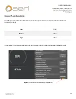
Страница 22: ...ivity The SRX ground fault detection offers three levels of sensitivity all of which are compliant with the Australian PV installation standards Low 100k Medium 50k High 30k The sensitivity of the gro...

Страница 23: ...for remote monitoring and control functionality The relevant protocol registry maps for integration are available from AERL on request Both networking protocols can be accessed via the RJ45 connector...

Страница 24: ...53 Low Input Voltage Detected Sleep Mode The PV Voltage is below the minimum allowed PV Voltage or not adequate to charge the connected battery Confirm PV String Configuration is appropriate for the d...

Страница 25: ...output voltage has been detected Confirm the battery is connected to the controller 1154 High Output Voltage High output voltage has been detected Battery may be being charged from a secondary source...

Страница 26: ...ature sensor has detected a low battery temperature Operating the battery at a low temperature may greatly reduce its lifespan Consider a temperature controlled battery environment if the battery regu...

Страница 27: ...ount Australian Energy Research Labs AER09 Rev 1 2 7th July 2022 27 AER09 REV 1 2 Note The CoolMax troubleshooting guide and documentation is being improved regularly If the relevant situation is not...

Отзывы: