20
7 MAINTENANCE
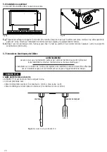
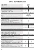
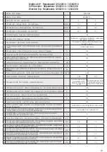
• Clean the pre-filters with a vacuum cleaner.
• Clean the G4 filters with a vacuum cleaner.
• Filters must be replaced every year. The actual need to perform this operation may vary depending on indoor and outdoor
ambient conditions.
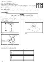
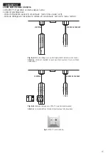
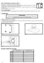
• Clean the diffuser (Fig. 7.a-b-c).
Fig. 7.c
WARNING
Make sure that the mains supply to the unit is disconnected before
performing any installation, service, maintenance or electrical work!
S1 S2 S3
II
I
I
Fig. 7.a
Fig. 7.b
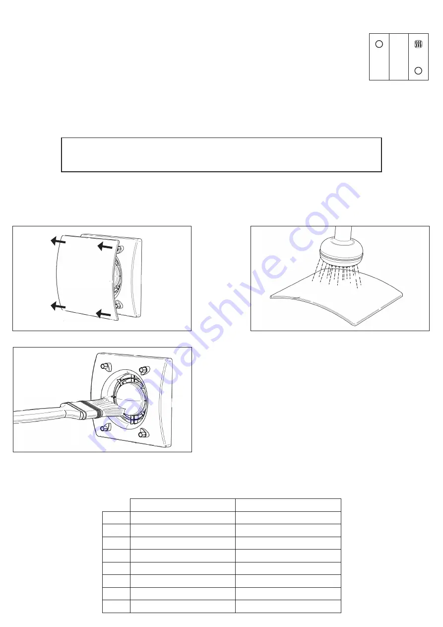
FILTER CLEANING
FILTER REPLACEMENT
DATE
DATE
DATE
DATE
DATE
DATE
DATE
DATE
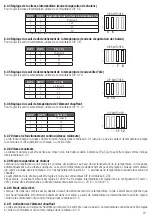
MAINTENANCE/CLEANING REGISTER
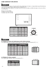
6.2.12 2 speed operation via CTRL-P1
S1 switch: the unit can be switched on (I) or off (O).
S2 switch: the continuous running (low) speed is activated by pressing position I; the maximum speed is
activated by pressing position II.
S3 switch : it activates the automatic operation of the heating element (AUTO) or deactivate it completely (O).
Wiring diagram as in Fig.5.k.
AUTO
6.2.13 Modbus control
The unit can be controlled via Modbus (Modbus RTU over RS485). For specification, contact our customer service.
switched as shown in table 6.2.6.


