AEM 30-8000 Скачать руководство пользователя страница 7

AEM Performance Electronics 

Phone (8am-5pm M-F PST): 310-484-2322 

2205 W 126

th 

Street, Unit A 

Fax: 310-484-0152 

Hawthorne, CA 90250 

[email protected] 

[email protected] 


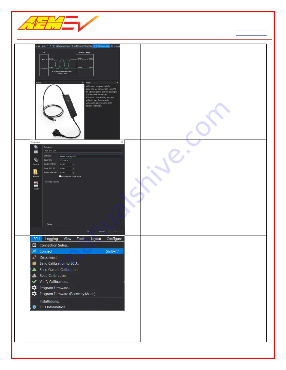
Select the PC Connection tab.  Assemble and add a PC 

communications stub to your harness.  Use the example 

schematic for reference.  The VCU200 communicates 

with your PC via a CAN to USB adapter.  If you do not 

have experience assembling harnesses for use in vehicle 

networks, please seek help from an experienced 

automotive harness builder.  The VCU200 functions as a 

CAN network data hub.  Proper network wiring is critical 

for performance and safety. 

1. Connect your CAN to USB adapter to an available 

USB port on your PC. 

2. Within AEMCal, go to ECU | Connection Setup… 

3. In the Port pane, ensure your settings match the 

example at left. 

4. Select your CAN to USB adapter from the CAN 

Port dropdown selection list.  If your device 

drivers were installed correctly, your adapter 

should appear in this list.  The example shows the 

Kvaser Leaf Light v2.  If it does not appear, try 

restarting AEMCal.  If you still have problems, 

there may be an issue with your adapter device 

driver installation.  Stop and contact the adapter 

manufacturer for troubleshooting support. 

1. Connect the power leads of your test harness to 

your 12V bench top power supply. 

2. Set the power supply current limit to 

approximately 1.0 amp. 

3. Turn the power supply switch on. 

4. Using your harness, turn the VCU ‘Key Switch’ on. 

5. At power up, the VCU should draw between 100 

and 500 mA depending on other loads present in 

the harness.  A lighted switch may create more 

current draw.  If the current is not within this 

range, double check your power distribution 

wiring. 

6. Connect the CAN to USB adapter to your harness 

DB9 communications interface. 

7. Go to ECU | Connect or the Shift+F7 hotkey 

combo.  AEMCal will attempt to connect to your 

VCU.  

6/3/2020, Revision C 

AEM EV VCU200 User Guide 

Page 

of 

15 

Содержание 30-8000

Страница 1: ...AEM Performance Electronics 2205 W 126 th Street Unit A Hawthorne CA 90250 Phone 8am 5pm M F PST 310 484 2322 Fax 310 484 0152 sales aemev com tech aemev com AEM EV VCU200 User Guide Revision C...

Страница 2: ...ou should refer the installation and calibration to a reputable installation facility or contact AEM EV for a referral in your area When access is required near the battery pack the cell segments must...

Страница 3: ...MAGES OF ANY AMOUNT OR CHARACTER INCLUDING WITHOUT LIMITATION ANY GENERAL INDIRECT SPECIAL INCIDENTAL EXEMPLARY CONSEQUENTIAL OR PUNITIVE DAMAGES ARISING OUT OF RELATED TO OR IN CONNECTION WITH 1 YOUR...

Страница 4: ...ility and other compatible 3rd party displays and data loggers About this document This document is not a comprehensive step by step guide to every feature available It is intended to get the VCU powe...

Страница 5: ...ly match the Version in the example image below Run the executable to install the hardware drivers It is always a good idea to restart your PC after installing new hardware drivers Please do so Harnes...

Страница 6: ...FactoryBase calibration which should be in the Documents AEM AEMcal Calibrations Factory folder 3 Load the Default200 layout file which should be in the Documents AEM AEMcal Layouts Factory folder 4...

Страница 7: ...ection list If your device drivers were installed correctly your adapter should appear in this list The example shows the Kvaser Leaf Light v2 If it does not appear try restarting AEMCal If you still...

Страница 8: ...and repeating the process If you got this far congratulations Your VCU is powered up and communicating with AEMCal Basic VCU Function Check AEMCal Work Space Tour 1 Within AEMCal navigate to the Setu...

Страница 9: ...uration Options There are several fundamental configuration settings required 1 Go to the Setup ConfigOptions group and select the Configuration tab 2 Select each setting and read the Description fiel...

Страница 10: ...your application Accelerator Pedal Select the AccelPedal tab This tab is large but for most applications there are only a handful of settings changes required The basic pedal calibration process is a...

Страница 11: ...the Brake Switch input to your VCU 3 Read the notes and Descriptions and configure for your application Drive Mode PRND Inputs Discrete PRND switch inputs are required for indirect drive applications...

Страница 12: ...ation faults can cause electric shock personal injury and even death An insulation monitoring device IMD must be used to protect against these faults See Bender https www benderinc com for more inform...

Страница 13: ...hannels These output functions are not re assignable 3 Manual override settings are available for testing each output Set the _OvrVal to 1 then set the _OvrSts to override to override the the output l...

Страница 14: ...channel 3 Configure the settings for your application The ContactorPreConditions channel list is helpful information for first time setups Read the Description for each channel and monitor during Inv...

Страница 15: ...nd a shipping service with package tracking capability Once your package is received by our warranty and repairs department you will be notified and provided with updates PROCEDURES FOR ISSUANCE OF A...

Отзывы: