background image

14

© 2015 AEM Performance Electronics

P/N 30-3500

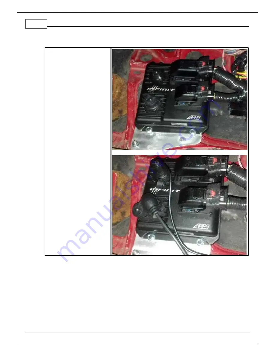
Step 5

Mount the Infinity ECU and
connect Infinity connectors and
USB cables. 

Step 6

Run the USB cables to an easily accessible location.

Step 7

Reconnect the battery's negative cable.

Содержание 30-3500

Страница 1: ... AND OR USE IT THE PURCHASER MUST ARRANGE TO RETURN THE PRODUCT FOR A FULL REFUND THIS POLICY ONLY APPLIES TO INSTALLERS AND OR USERS WHO ARE LOCATED IN THE UNITED STATES HOWEVER CUSTOMERS WHO RESIDE IN OTHER COUNTRIES SHOULD ACT IN ACCORDANCE WITH THEIR LOCAL LAWS AND REGULATIONS WARNING This installation is not for the tuning novice Use this system with EXTREME caution The AEM Infinity Programma...

Страница 2: ...a Supra MKIV Twin Turbo base sessions are located in C Documents AEM Infinity Tuner Sessions Base Sessions DOWNLOADABLE FILES Files can be downloaded from www aeminfinity com An experienced tuner must be available to configure and manipulate the data before driving can commence The Quick Start Guide and Full Manual describe the steps for logging in and registering at www aeminfinity com These docu...

Страница 3: ... attempting any modifications The entire Molex MX123 User Manual can be downloaded direct from Molex at http www molex com mx_upload family MX123UserManual pdf INFINITY ADAPTER HARNESS Included with the 1993 1998 Toyota Supra MKIV Twin Turbo kit is an adapter harness This is used to make the connection between the AEM Infinity EMS and the Toyota wiring harness plug and play This is depicted below ...

Страница 4: ... P N 30 3500 ECU SETUP WIZARD Important Application Specific Settings Engine In the Wizard Engine tab confirm the following Number of Cylinders 6 Engine Cycle Type 4 Stroke Ignition Type Sequential Coil On Plug Firing Order 1 5 3 6 2 4 ...

Страница 5: ...e following Ignition Sync Add a text grid control to your layout and select the following channels Make sure their values match the settings below for initial timing sync TrigOffset degBTDC 23 00 CamSyncAdjustment 11 00 See QuickStart Guide section Setup Ignition Sync for instructions on timing sync Idle Stepper Max Steps Go to Setup Wizard Idle page and confirm the following Idle Stepper Max Step...

Страница 6: ...6 pin connector and MUST be modified See instructions below A Bipolar Stepper Motor e g GM will have a 4 pin connector and DOES NOT need to be modified This info does not apply to vehicles that utilize IACV solenoids The 2 center pins Black Red wires supply 12V power to the stepper motor in the factory setup however these pins MUST BE DISCONNECTED before powering the AEM Infinity ECU ...

Страница 7: ...ance Electronics Step 1 Disconnect connector from IACV housing and gently remove the retainer from the connector Step 2 Use a small flat blade screwdriver pick to move the terminal locks while pulling the Black Red wires out from the backside of the connector ...

Страница 8: ...rformance Electronics P N 30 3500 Step 3 Use heat shrink to insulate both 12V wires and then zip tie the insulated wires to a nearby loom Step 4 Reinstall the retainer and then plug the connector back into the IACV ...

Страница 9: ...nce Electronics MAIN RELAY FUEL PUMP SCHEMATIC The 1993 1998 Toyota Supra Infinity patch harness requires a harness relay and fuel pump control to be wired exactly as pictured below Failure to do so may result in an unresponsive ECU and or a no start condition ...

Страница 10: ...anel Toyota PN 55199 14020 could potentially result in damage to the ECU adapter harness ECU connectors and or USB cables and connectors Please note clearance modifications below These modifications should be performed with a die grinder 90 degree sander or plastic shears Step 1 Remove the four ribs located near the center of the cover as highlighted below Step 2 Trim the center support leg as out...

Страница 11: ...015 AEM Performance Electronics INFINITY EMS INSTALLATION Step 1 Disconnect battery s negative cable Step 2 Locate factory Engine Control Unit ECU Most ECU s are located in the passenger kick panel behind the center console or in the engine bay ...

Страница 12: ...12 2015 AEM Performance Electronics P N 30 3500 Step 3 Unplug factory harness plugs at ECU and remove factory ECU ...

Страница 13: ...1993 1998 Toyota Supra MKIV Twin Turbo 13 2015 AEM Performance Electronics Step 4 Plug factory harness plugs into AEM Infinity Adapter Harness ...

Страница 14: ...rformance Electronics P N 30 3500 Step 5 Mount the Infinity ECU and connect Infinity connectors and USB cables Step 6 Run the USB cables to an easily accessible location Step 7 Reconnect the battery s negative cable ...

Страница 15: ... with internal f ly back diode Inductiv e load should NOT hav e f ull time power See Setup Wizard Page LowSide Assignment Tables f or output assignment and 2D table LS6_Duty f or activ ation C1 4 UEGO 1 Heat UEGO 1 Heat Bosch UEGO controller Lowside switch f or UEGO heater control Connect to pin 4 of Bosch UEGO sensor NOTE that pin 3 of the Sensor is heater and must be power by a f used switched 1...

Страница 16: ...NOT connect directly to coil primary Must use an ignitor OR CDI that accepts a FALLING edge f ire signal C1 15 Coil 6 Coil 6 25 mA max source current 0 5V Falling edge f ire DO NOT connect directly to coil primary Must use an ignitor OR CDI that accepts a FALLING edge f ire signal C1 16 Coil 5 Coil 5 25 mA max source current 0 5V Falling edge f ire DO NOT connect directly to coil primary Must use ...

Страница 17: ...igital_In_5 Flex Fuel 10K pullup to 12V Will work with ground or f loating switches See channel FlexDigitalIn Hz f or raw f requency input data C1 27 Knock Sensor 1 Knock Sensor 1 Dedicated knock signal processor See Setup Wizard page Knock Setup f or options C1 28 Knock Sensor 2 Knock Sensor 2 Dedicated knock signal processor See Setup Wizard page Knock Setup f or options C1 29 12V_Relay _Control...

Страница 18: ...as this can permanently damage the ECU See the Setup Wizard Fuel Pressure page f or setup and calibration Monitor the FuelPressure psig channel C1 38 Analog_In_10 Baro Sensor 12 bit A D 100K pullup to 5V 0 5V analog signal Use 5V Out pins as power supply and Sensor Ground pins as the low ref erence Do not connect signals ref erenced to 12V as this can permanently damage the ECU See the Setup Wizar...

Страница 19: ...ion Sensor VR Crankshaf t Position Sensor VR See Setup Wizard page Cam Crank f or options C1 47 Camshaf t Position Sensor 1 VR Camshaf t Position Sensor 1 VR Dif f erential Variable Reluctance Zero Cross Detection See Setup Wizard page Cam Crank f or options C1 48 Camshaf t Position Sensor 1 VR Camshaf t Position Sensor 1 VR See Setup Wizard page Cam Crank f or options C1 49 VR _In_2 Non Driv en L...

Страница 20: ...ture Setup Wizard f or selection C1 67 Analog_In_Temp_2 Intake Air Temperature 12 bit A D 2 49K pullup to 5V See Air Temperature Setup Wizard f or selection C1 68 Harness_Analog_In_Tem p_3 Oil Temperature Sensor 12 bit A D 2 49K pullup to 5V See 1D table OilTempCal table f or calibration data and OilTemp C f or channel data C1 69 Stepper_2A Stepper 2A Automotiv e Programmable Stepper Driv er up to...

Страница 21: ...C1 29 abov e C2 10 Injector 11 Injector 11 Saturated or peak and hold 3A max continuous Not used C2 11 Injector 12 Injector 12 Saturated or peak and hold 3A max continuous Not used C2 12 Analog_In_17 A C Analog Request 12 bit A D 100K pullup to 5V 0 5V analog signal Use 5V Out pins as power supply and Sensor Ground pins as the low ref erence Do not connect signals ref erenced to 12V as this can pe...

Страница 22: ...commended C2 20 Analog_In_15 Exhaust Back Pressure 12 bit A D 100K pullup to 5V 0 5V analog signal Use 5V Out pins as power supply and Sensor Ground pins as the low ref erence Do not connect signals ref erenced to 12V as this can permanently damage the ECU See Setup Wizard Exhaust Pressure page f or setup options See EBPress kPa f or channel data C2 21 Analog_In_16 DBW1_TPSB 12 bit A D 100K pullup...

Страница 23: ...f erenced to 12V as this can permanently damage the ECU See 3StepSwitch 1 axis table f or setup C2 35 Analog_In_22 USB Logging Activ ate 12 bit A D 100K pullup to 5V 0 5V analog signal Use 5V Out pins as power supply and Sensor Ground pins as the low ref erence Do not connect signals ref erenced to 12V as this can permanently damage the ECU See USBLoggingRequestIn channel f or input state See Setu...

Страница 24: ...GPIOs and PWM Setup Wizard page LowSide Assignment Tables f or additional options C2 45 UEGO 2 VM UEGO 2 VM Bosch UEGO Controller Virtual Ground signal Connect to pin 5 of Bosch UEGO sensor C2 46 UEGO 2 UN UEGO 2 UN Nernst Voltage signal Connect to pin 1 of Bosch UEGO sensor C2 47 UEGO 2 IP UEGO 2 IP Pumping Current signal Connect to pin 6 of Bosch UEGO sensor C2 48 UEGO 2 IA UEGO 2 IA Trim Curren...

Страница 25: ...directly to coil primary Must use an ignitor OR CDI that accepts a FALLING edge f ire signal C2 55 Highside Fuel Pump switch Fuel Pump Highside switch 0 7A max Solid State Relay NO internal f ly back diode 12V High Side Driv e Will prime f or 2 seconds at key on and activ ate if RPM 0 C2 56 Not used Not used Not used Not used Aux Connector Pinout DTM 12 Pin Connector Infinity 10 1 C1 37 Analog_In_...

Страница 26: ...26 2015 AEM Performance Electronics P N 30 3500 Infinity Pin Numbering AEM Infinity Connectors Viewed from Wire Side ...

Страница 27: ... installation accident abuse unauthorized repairs or alterations voids this warranty AEM disclaims any liability for consequential damages due to breach of any written or implied warranty on all products manufactured by AEM Warranty returns will only be accepted by AEM when accompanied by a valid Return Merchandise Authorization RMA number Product must be received by AEM within 30 days of the date...

Отзывы: