background image

3

30-0311 - OBD-II

Operation

View Parameter IDs (PIDs)

Depress the PAGE button to scroll through the available OBD-II PIDs/parameters; an
abbreviation of each parameter name will be briefly displayed after each button press.
  The  inner  numeric  LEDs  and  outer  ring  LED  display  the  currently  selected
parameter reading.  Please reference the supported OBD-II PID description table
further on in this document.  The gauge is capable of displaying all the PIDs listed in
this table, however, the PID must be available on your specific vehicle.  Not all PIDs
are available on all vehicles.  

PAGE and DTC buttons are located on the face of the gauge and are used to perform
various functions, described below.

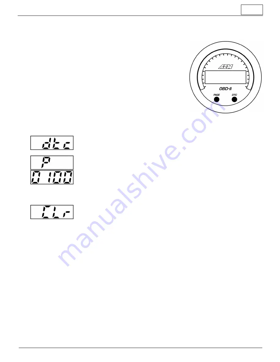
Display or clear stored DTC (Diagnostic Trouble Codes)

§

After pressing the DTC button, "dTC" will be briefly be displayed.

§

If no DTCs are available, "nonE" will be displayed.

§

If DTCs are available, the gauge will begin displaying the codes  by  briefly  displaying
the


alphabetic prefix and then the numeric suffix.

§

DTC codes have a standardized format; one letter followed by four numbers, e.g. P0030.

§

For example, a P0030 code will be displayed as first "P" and then "0030".

§

Briefly pressing the DTC button will scroll through the stored codes if there are more than
one.

§

Depress and hold the DTC button, while viewing the DTCs, to clear them.

§

Some vehicles require the engine be off to clear codes.  In this  case,  start  the engine to
wake up the gauge, turn off the engine but return the key to the "run" position so the ECU
is on.  Immediately after, follow the procedure to clear the DTCs before the gauge goes
to


sleep.

§

Alternatively, if you don't wish to start the engine, you may unplug the gauge from the OBD
port and plug it back in to wake up the gauge,  turn the key  to Run,  and then follow
the


procedure to clear DTCs.

§

The gauge will return to normal display mode a few seconds after the last button press

Change display units US / SI (metric)

§

The gauge should be in its normal display mode, showing the current parameter reading

§

Depress and hold both the PAGE button for three seconds until US or SI appears

§

Press the PAGE button to toggle between US or SI (metric) modes

§

The gauge will return to normal display mode a few seconds after the last button press

Содержание 30-0311

Страница 1: ...THE MISUSE OF THIS PRODUCT Instruction Manual Features 2 1 16 52mm outer diameter mounting Only model year 2008 and newer vehicles CAN bus based OBD supported 41 OBD II parameters PIDs supported Read and clear Diagnostic Trouble Codes DTCs US or Metric SI display modes Black bezel faceplate supplied Silver white available as optional purchase Locking connectors Auto dimming Supports vehicle system...

Страница 2: ...D2 port is a permanent always on 12V no key switched power is available at this port The AEM X Series OBD2 Gauge uses a specific algorithm to detect when the key is on and the engine is started to wake up or go to sleep down conserving power The engine must be running for the gauge to remain on and display information NOTE It is advised to unplug the gauge from the OBD port if the vehicle is to be...

Страница 3: ... standardized format one letter followed by four numbers e g P0030 For example a P0030 code will be displayed as first P and then 0030 Briefly pressing the DTC button will scroll through the stored codes if there are more than one Depress and hold the DTC button while viewing the DTCs to clear them Some vehicles require the engine be off to clear codes In this case start the engine to wake up the ...

Страница 4: ...ive scalings on either side Reference the Operation section of this manual for details on how to switch the display mode when reversing the faceplate Disassembly is required to change the faceplate flip reverse the faceplate or change the bezel of the gauge The following diagram will provide familiarization with the major components of the gauge prior to beginning the procedure Item Qty Descriptio...

Страница 5: ...existing bezel at this time STEP 2 Separate the PCB 11 from the remaining components STEP 3 Slide the light guide 5 upward to remove it the buttons may fall out at this time take care not to lose them STEP 4 As you separate the remaining components diffuser 4 faceplate 3 lens 1 note the order in which they were assembled The faceplate 3 may now be reversed to display an alternate scaling or replac...

Страница 6: ...P 2 Stack the diffuser 4 faceplate 3 and lens 1 in order over the buttons and on to the light guide STEP 3 Reassemble the PCB and display stack with the bezel making sure screw holes are aligned through the entire assembly STEP 4 Reassemble and tighten screws to 2 in lb previously assembled bezel or 3 in lb new bezel Do not over tighten ...

Страница 7: ... MAF air flow rate lb min g sec 0F Air t Intake air temp degF degC 46 Air t Ambient air temp degF degC 68 Air t Intake air temp sensor degF degC If 0F is n a 33 bAro Barometric pressure abs psi kPa 42 bAtt Control Module Voltage V V 05 Cl t Engine coolant temp degF degC 23 d Prs Fuel Rail Pr die or gdi kpsi bar If 0A 22 are n a 59 d Prs Fuel Rail Pr die or gdi kpsi bar 6D d Prs Fuel Rail Pr die or...

Страница 8: ...t when I scroll through the PID list using the PAGE button Your vehicle may not support every PID that is supported by the AEM OBD II gauge Upon power up the gauge will query the vehicle for a list of the available PIDs and display the ones which are supported by the gauge If the PID is not listed when scrolling through the list using the PAGE button then the PID is not supported by your vehicle M...

Страница 9: ...s advised to unplug the gauge from the OBD port if the vehicle is to be stored for long periods of time to avoid excess drain on the battery What pins are used in the connector To populate optional extras use JST P N SPUD 001T P0 5 terminals for 22 26 AWG wire Specifications Dimensions diameter bezel 2 40 in diameter cup 2 1 16 in depth incl bezel 0 825 in depth cup only 0 200 in Supply Voltage mi...

Отзывы: