ᆅჾ
ۉጱྃ੩ഗ
ॲ
֪
য়ߢ
༵๖
ణ
INTRO
TRIP UNIT
LOCKS
ACCESSORIES
TESTS
APPENDIX
1.3-03
ᆅჾ
ࡀ߭
Ҿጎ
֡ፕ
ۉጱྃ੩ഗ
ୟഗ
BREAKER
NF1:ဣଚگუഘୟഗ
2/4/2!༵ืࢅҾጎ
๑ᆩ༵ืכࢅದഗጎዃLjᆩᇀᅎۯୟഗăದ
ഗᆩᇀᅎۯॐ!4!႙ୟഗă
2/4/3!ࠦۨ๕ୟഗҾጎ
2/! ඓԍୟഗฉݛᆶፁࠕڦक़ဤLjᅜՍָأ௶ࢷቸLjॠֱ
௶ࢷةۅă
3/!๑ᆩ!5!߲!N9!அພᅜ!36!On!ڦ౦ਈॽୟഗࠦۨڟ
ࢇڦኧॐࠓฉă
4/!ୟഗᅃ֨Քऻᆶൣညڦথںۅă
2/4/4!؏๕ୟഗҾጎ
؏๕ୟഗཚᅜҾጎڟ؏ॐฉڦႚ๕ऋă
2/!Ӏቷ!2/5!বዐຎڦ؏ײႾॽୟഗٗ؏ॐዐൽă
3/! ߵᄲ൱ॽ؏ॐࠦۨሞದۉಎฉă؏ॐᅜᆩ༵ืLj
ڍසࡕ๑ᆩ༵ืכईഄ༵ืጎዃLj൩๑ᆩ࿋ᇀ؏ॐኟ
௬ࢅԝ௬ڦඇև
5!߲༵ืă
4/! ॽ؏ॐࠦۨڟ࿋Ljথᆅࢅᆅڦۉમ0జಇăথ
జಇ้Ljඓԍ؏ॐࢫ௬ڦೋֶ0ᆌ૰ྺፌၭă
5/!๑ᆩ!5!߲!N9!அພᅜ!36!On!ڦ౦ਈॽ؏ॐҾጎڟኟ
௬ࢅԝ௬Ҿጎۅฉă
6/!ॠֱҾጎǖ
..!ඓԍ؏ॐڹፗೝ།Ljॐྺኟݛႚă
..!ඓԍҾඇڔӱᅜሞҾጎஅພྜඇౣࢫጲᆯᅎۯă
7/!Ӏቷ!2/5!বዐڦຫ߸࣑؏ॐాڦยԢă
8/!Ⴔᄲ้Lj؏ॐଇ֨Քऻᆶൣညڦথںۅă
1.3 INSTALLATION
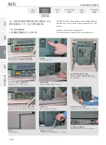
Using a Li
Ō
ing Truck and Adapter Op
Ɵ
onally available to
facilitate breakers handling. an adapter being available
allowing one to use the same device for envelope 3 devices.
1.3.2 Fixed Circuit Breaker Installa
Ɵ
on
1. Ensure adequate clearance above the circuit breaker to
allow removal of the arc chutes and inspec
Ɵ
on of the arcing
contacts.
2. Fasten the circuit breaker into posi
Ɵ
on on a suitable support
structure using four M8 bolts, torque to 25 N m.
3. A clearly marked grounding point is provided on either side
of the circuit breaker.
1.3.3 Drawout Circuit Breaker Installa
Ɵ
on
Drawout type circuit breakers are normallydelivered already
mounted in casse
Ʃ
es.
1. Remove the circuit breaker from its casse
Ʃ
e using
withdrawal procedures described in Sec
Ɵ
on 1.4.
2. Posi
Ɵ
on the casse
Ʃ
e as required in the switchboard. The
casse
Ʃ
e may be li
Ō
ed by hand; however, if a handling truck or
other li
Ō
ing gear is used, use all four li
Ō
ing holes provided at
front and rear of the casse
Ʃ
e.
3. Posi
Ɵ
on casse
Ʃ
e in place and connect incoming and
outgoing cables/busbars. Ensure there is minimal
de
Ň
ec
Ɵ
on/stress to the back of the casse
Ʃ
e when connec
Ɵ
ng
busbars.
4. Mount the casse
Ʃ
e using four M8 bolts andtorque to 25 N m
at the front and rear moun
Ɵ
ng points.
5. Check the moun
Ɵ
ng to:
-- Ensure the casse
Ʃ
e base is
Ň
at and the frame is square.
-- Ensure the safety shu
Ʃ
ers move freely a
Ō
er the moun
Ɵ
ng
bolts have been fully
Ɵ
ghtened.
6. Replace the Device in the casse
Ʃ
e as described in sec
Ɵ
on
1.4.
7. If needed, a clearly marked grounding point is provided on
both sides of the casse
Ʃ
e.
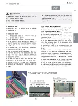
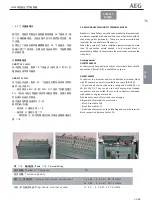
!2/4ǖդ࿋ዃ
Gjh/!2/4;!Iboe!Hsjq!Mpdbujpo
!2/5ǖ༵ืۗܺ
Gjh/!2/5;!Mjgujoh!Fzft
$


