background image

27

TS-207 User Manual

C

ha

pte

r 5
BIO

S S

ett

ing

s

5.2

Entering Setup

Turn on the computer and then press <F2> or <DEL> to enter the Setup menu.

5.2.1

Main Setup

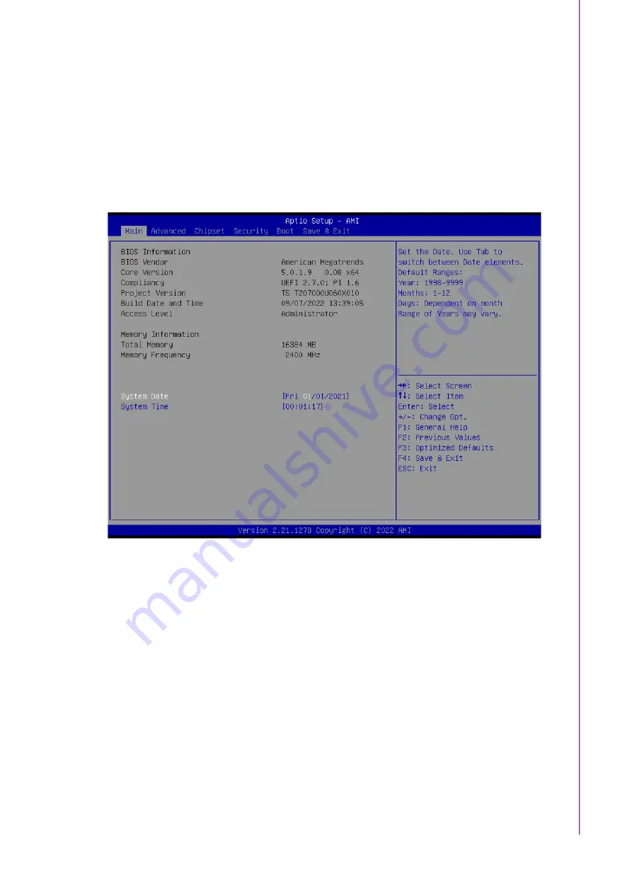
When you first enter the BIOS Setup Utility, you will enter the Main setup screen. You

can always return to the Main setup screen by selecting the Main tab. There are two

Main Setup options. They are described in this section. The Main BIOS Setup screen

is shown below.

Figure 5.2 Main Setup Screen

The Main BIOS setup screen has two main frames. The left frame displays all the

options that can be configured. Grayed-out options cannot be configured; options in

blue can. The right frame displays the key legend.
Above the  key legend is  an area reserved  for  a  text message. When an  option  is

selected in the left frame, it is highlighted in white. Often a text message will accom

-

pany it.

System Time/System Date

Use this option to change the system time and date. Highlight System Time or 

System Date using the <Arrow> keys. Enter new values through the keyboard. 

Press the <Tab> key or the <Arrow> keys to move between fields. The date 

must be entered in MM/DD/YY format. The time must be entered in HH:MM:SS 

format.

Содержание TS-207

Страница 1: ...User Manual TS 207 Fanless Embedded Computer with IP65 Rated Enclosure ...

Страница 2: ...ownload the latest English user manual and drivers on website https www advantech tw products 1 flnuyz TS 207 mod_fbd3dc60 12e1 41f6 978b d74bdd128da4 Please disregard the printed Chinese copy of the user manual if the product is not to be sold and or installed in China 甲類警語 警告使用者 這是甲類資訊產品 在居住的環境中使用時 可能會造成射 頻干擾 在這種情況下 使用者會被要求採取某些適當對策 ...

Страница 3: ...ssumes no liability under the terms of this warranty as a consequence of such events Because of Advantech s high quality control standards and rigorous testing most customers never need to use our repair service If an Advantech product is defective it will be repaired or replaced free of charge during the warranty period For out of warranty repairs customers will be billed according to the cost of...

Страница 4: ...terference to radio communications However there is no guarantee that interfer ence will not occur in a particular installation If this equipment does cause harmful interference to radio or television reception which can be determined by turning the equipment off and on the user is encouraged to try to correct the interference by one or more of the following measures 1 Reorient or relocate the rec...

Страница 5: ... HU 001 Industrial GPS NEO M9N GPS BeiDou Galileo GLONASS half sized mini PCIe module operating temperature 40 85 C 96PSA A120W24T2 3 Power adapter A D 100 240V 120W 24V C14 CORD 1702002600 Power cable 3 pin 180 cm USA type 1702002605 02 Power cable 3 pin 183 cm Europe type 1700018704 Power cable 3 pin 183 cm UK type 1700033565 01 Power adapter cable M12 to 6 PIN terminal block for power adapter W...

Страница 6: ...id into an opening This may cause fire or electrical shock 13 Never open the equipment For safety reasons the equipment should be opened only by qualified service personnel 14 If any of the following occurs have the equipment checked by service person nel The power cord or plug is damaged Liquid has penetrated the equipment The equipment has been exposed to moisture The equipment is malfunctioning...

Страница 7: ...le net toyage 4 Pour les équipements enfichables la prise de courant doit être située près de l équipement et doit être facilement accessible 5 Gardez cet équipement à l abri de l humidité 6 Placez cet équipement sur une surface fiable pendant l installation Le laisser tomber ou le laisser tomber peut provoquer des dommages 7 Les ouvertures du boîtier sont destinées à la convection d air Protégez ...

Страница 8: ... alimentation de votre châssis lorsque vous travaillez avec le matériel N établissez pas de con nexions lorsque l appareil est sous tension Les composants électroniques sen sibles peuvent être endommagés par des surtensions soudaines 18 ATTENTION mettez vous toujours à la terre pour éliminer toute charge statique avant de toucher la carte mère le fond de panier ou les cartes d extension Les appare...

Страница 9: ...in Board 15 Table 3 1 Clear CMOS CMOS1 15 3 2 2 Power Board 15 Table 3 2 Power Input Mode 15 3 3 Connector Settings 15 3 3 1 Main Board 15 Table 3 3 SATA Connector 15 Table 3 4 SATA power Connector 16 Table 3 5 Audio Connector 16 3 4 Switch Settings 16 3 4 1 Main Board 16 Table 3 6 Power Settings for MiniPCIe2 16 3 4 2 Power Board 17 Table 3 7 Power Ignition 17 Table 3 8 Power Ignition SW HW Setti...

Страница 10: ...34 Figure 5 10Firmware Update Configuration 35 Figure 5 11Trusted Computing 36 Figure 5 12ACPI Settings 37 Figure 5 13Embedded Controller 38 Figure 5 14PC Health Status 39 Figure 5 15 Serial Port 2 Configurations 39 Figure 5 16Serial Port Console Redirection 40 Figure 5 17USB Configuration 41 Figure 5 18NVMe Configuration 42 Figure 5 19Network Stack Configuration 43 Figure 5 20Network Stack Config...

Страница 11: ...xi TS 207 User Manual 6 1 S W Introduction 60 6 2 Driver Installation 60 6 2 1 Windows Driver Setup 60 6 2 2 Other OS 60 6 3 Advantech iManager 60 ...

Страница 12: ...TS 207 User Manual xii ...

Страница 13: ...Chapter 1 1 General Introduction This chapter details background information for the TS 207 series ...

Страница 14: ...mory down and 32GB SO DIMM This solution also integrates 11th Gen Intel Core processors Iris Xe Graphics to empower up to 2 x independent 4K displays and further pro vides support 4 x IEEE802 3af PoE ports with a maximum power output of 60W for IP camera surveillance applications In addition this series features Advantech s iMan ager SUSI4 software This software meets embedded application requirem...

Страница 15: ...deo API DXVA2 Direct3D 12 Video API Intel Media SDK MFT Media Foundation Transform filters Intel VA API BIOS AMI EFI 256 Mbit System memory 1 x SO DIMM socket up to 32GB DDR4 Dual channel 3 200 MT S Onboard 8GB for Intel i5 CPU skue only Storage mSATA 1 x full size mSATA storage leverage mPCIe slot Onboard NVMe SSD up to 32 GB support by project Serial Ports 2 x DB 9 Isolated RS 232 422 485 ports ...

Страница 16: ... support by project Enclosure Black aluminum housing Operating temperature With extended temperature peripherals 40 70 C with 0 7m s air flow With standard temperature peripherals 0 60 C with 0 7m s air flow Storage temperature 40 85 C 40 185 F Relative humidity 95 40 C non condensing IP Rating IP65 water dust proof Certifications EMC CE FCC Class B Safety 12V and 24V DC E Mark E13 Additional for ...

Страница 17: ...5 TS 207 User Manual Chapter 1 General Introduction 1 4 Dimensions Figure 1 1 TS 207 Dimensions ...

Страница 18: ...TS 207 User Manual 6 ...

Страница 19: ...2 Hardware Installation This chapter introduces the instal lation of TS 207 hardware Chapter 2 ...

Страница 20: ...ted protection Remove 14 screws in total to install accessories on the button side of the board and please use a torque screwdriver to lock the 14 screws with torque value 8 0 0 5 kgf cm after installing Warning Do not remove the aluminum covers until verifying that no power is flow ing within the computer Power must be switched off and the power cord must be unplugged Take care in order to avoid ...

Страница 21: ...ation Install accessories on the button side of the board 2 3 SATA and Power Please check that SATA cable power cable and 2 5 HDD mounting kit are ready before set up If any item does not accord with the table please contact your dealer immediately ...

Страница 22: ...se contact Advantech if you want to expand your memory capacity 2 5 Installing Audio This project requires customized enclosure and support based on specific needs Please contact Advantech to inquire further about our project based support ser vices ...

Страница 23: ...er explains how to set up TS 207 Series hardware including instructions on setting jumpers and connecting peripher als and how to set switches and read indicators Be sure to read all the safety pre cautions before beginning the installation procedure ...

Страница 24: ... them To close a jumper connect the pins with the clip To open a jumper remove the clip Sometimes a jumper has three pins labeled 1 2 and 3 In this case connect either pins 1 and 2 or pins 2 and 3 A pair of needle nose pliers may be helpful when working with jumpers If there are any doubts about the best hardware configuration for the application contact the local distributor or sales representati...

Страница 25: ...Top View of Jumpers and Switches Reserved for user setup Jumpers Description CMOS1 Clear CMOS J1 Power board Power input mode Powered by power adapter or in vehicle power SW1 Power board Power ignition control switch Connector Description SATA1 SATA connector SATA_PW1 SATA power Connector SW4 Power settings for miniPCIe2 AUDIO1 Audio connector ...

Страница 26: ...ging Figure 3 2 Top View of Reserved Connectors Connector Description SW1 Power switch with power LED CN6 SMBus and UART Reserved for power board DCIN_12V1 DC input CN4 Power Board Reset button CN1 Power Board SMBus System ON OFF control CN2 Power Board Power button ...

Страница 27: ...V for in vehicle and P is for power adapter 3 3 Connector Settings 3 3 1 Main Board 3 3 1 1 SATA Connector SATA1 Table 3 1 Clear CMOS CMOS1 Setting Function 1 2 Normal default 2 3 Clear CMOS Table 3 2 Power Input Mode Setting Function 1 2 V mode In vehicle mode default 2 3 P mode power adapter Table 3 3 SATA Connector Pin Signal Name Pin Signal Name 1 GND 2 SATA0_TX 3 SATA0_TX 4 GND 5 SATA0_RX 6 S...

Страница 28: ...er Settings for miniPCIe2 SW4 Table 3 4 SATA power Connector Pin Signal Name Pin Signal Name 1 5V 2 GND Table 3 5 Audio Connector Pin Signal Name Pin Signal Name 1 LINEOR 2 LINE1R 3 GND 4 GND 5 LINEOL 6 LINE1L 7 GND 8 GND 9 MIC1R 10 MIC1L Table 3 6 Power Settings for MiniPCIe2 Setting Function ON Standard MiniPCIe default OFF Support ME909s ...

Страница 29: ... 3 Ignition ON Timer Ignition OFF Delay Timer Ignition OFF Delay Timer H W shutdown OFF OFF OFF 7 default 30 default 180 default ON OFF OFF 10 40 180 OFF ON OFF 10 60 180 OFF ON ON 30 60 180 OFF OFF ON 60 120 180 ON OFF ON 120 180 180 OFF ON ON 180 240 180 ON ON ON 7 0 180 Table 3 8 Power Ignition SW HW Setting Selection Setting Function Off Power Ignition SW settings On Power Ignition HW settings...

Страница 30: ...TS 207 User Manual 18 ...

Страница 31: ...Chapter 4 4 Pin Assignments This chapter details Pin Assign ments for the TS 207 Series ...

Страница 32: ...efinition 4 2 1 Power Input Connector TS 207 comes with 4 pin M12 A code power input connector for 12 24 V DC Input for in vehicle or 24V DC input for railway applications Figure 4 1 Power Input Connector Table 4 1 Connector Pin Assignments Pin Signal Name Pin Signal Name 1 V12 2 V12 3 GND 4 GND ...

Страница 33: ...N OFF Button 4 2 3 HDMI Connector TS 207 provides 2 x HDMI ports with resolution that can support up to 4K x 2K at 48 60 Hz 24bpp Figure 4 3 HDMI Connector Table 4 2 HDMI Display Port Connector Pin Assignments Pin Signal Name Pin Signal Name 1 TMDS_Data2 DP_Data0 2 GND 3 TMDS_Data2 DP_Data0 4 TMDS_Data1 DP_Data1 5 GND 6 TMDS_Data1 DP_Data1 7 TMDS_Data0 DP_Data2 8 GND 9 TMDS_Data0 DP_Data2 10 TMDS_...

Страница 34: ...X code circular connectors with USB 2 0 support Figure 4 4 USB 3 0 Connector Figure 4 5 USB 2 0 with M12 Connector Table 4 3 USB 3 0 Connector Pin Assignment Pin Signal Name Pin Signal Name 1 5V 2 D 3 D 4 GND 5 SSRX 6 SSRX 7 GND 8 SSTX 9 SSTX 10 5V 11 D 12 D 13 GND Table 4 4 USB 2 0 Connector Pin Assignment Pin Signal Name Pin Signal Name 1 5V 2 GND 3 Data 4 Data ...

Страница 35: ...es 2 x D sub 9 pin connectors which offers 2 x RS 232 422 485 serial communication ports with 3 KV isolation and auto flow control The setting of protocol can be configured via the BIOS settings Figure 4 7 COM Port Connector Table 4 5 Connector Pin Assignments Pin Signal Name Pin Signal Name 1 LAN_M0 2 LAN_M1 3 LAN_M3 4 LAN_M2 5 LAN_M0 6 LAN_M1 7 LAN_M3 8 LAN_M2 Table 4 6 COM Connector Pin Assignm...

Страница 36: ...TS 207 User Manual 24 ...

Страница 37: ...Chapter 5 5 BIOS Settings BIOS Configuration data setup ...

Страница 38: ... control the various sys tem features This chapter describes the basic navigation of the TS 207 BIOS setup screens Figure 5 1 Setup Program Initial Screen AMI s BIOS ROM has a built in setup program that allows users to modify the basic system configuration This information is stored in battery backed CMOS so it retains the setup information when the power is turned off ...

Страница 39: ... has two main frames The left frame displays all the options that can be configured Grayed out options cannot be configured options in blue can The right frame displays the key legend Above the key legend is an area reserved for a text message When an option is selected in the left frame it is highlighted in white Often a text message will accom pany it System Time System Date Use this option to c...

Страница 40: ... the left frame of the screen such as CPU Configuration to go to the sub menu for that item You can display an Advanced BIOS Setup option by highlighting it using the Arrow keys All Advanced BIOS setup options are described in this section The Advanced BIOS Setup screens are shown below The sub menus are described on the following pages Figure 5 3 Advanced BIOS Features Setup Screen ...

Страница 41: ...CPI Settings Enable ACPI Auto Configuration Enables or Disables BIOS auto configuration Enable Hibernation Enables or Disables system ability to Hibernate OS S4 sleep state ACPI Sleep State Select the highest ACPI sleep state the system will enter when the SUSPEND button is pressed ...

Страница 42: ...iveProcessorCore Number of cores to enable in each processor package Hyper Threading Enables or Disables Hyper Threading configuration AES Enables or Disables AES configuration MonitorMWait Enables or Disables MonitorMWait configuration IntelTrustedExecution Technology Enables or Disables IntelTrustedExecution configuration ...

Страница 43: ...31 TS 207 User Manual Chapter 5 BIOS Settings 5 2 2 3 Power Performance Figure 5 5 Power Performance CPU Power Management Control GT Power Management Control ...

Страница 44: ...ntrol Boot performance mode Max Battery Max Non Turbo Performance Turbo Performance Intel SpeedStep Enable Disable Turbo Mode Enable Disable Config TDP Configurations C states Enable Disable Configurable TDP Boot Mode Nominal Up Down Deactivate TDP selection ...

Страница 45: ...33 TS 207 User Manual Chapter 5 BIOS Settings Figure 5 7 Configurable TDP Boot Mode GT Power Management Control Disable Enable Figure 5 8 GT Power Management Control ...

Страница 46: ...ender standby support 5 2 2 4 PCH FW Configuration Figure 5 9 PCH FW Configuration ME Firmware Version Mode SKU Status 1 Status 2 ME State Disable Enable ME Unconfig on RTC Clear Disable Enable Firmware Update Configuration Me FW Image Re Flash Disable Enable ...

Страница 47: ...35 TS 207 User Manual Chapter 5 BIOS Settings Figure 5 10 Firmware Update Configuration ...

Страница 48: ...ank Disable Enable SHA256 PCR Bank Disable Enable Pending operation None TPM Clear Platform Hierarchy Disable Enable Storage Hierarchy Disable Enable Endorsement Hierarchy Disable Enable TPM 2 0 VEFI Spec Version TCG_1_2 TCG_2 Physical Presence Spec Version 1 2 1 3 TPM 2 0 InterfaceType CRB TIS Device Select Auto Enable Disable ...

Страница 49: ...er 5 BIOS Settings 5 2 2 6 ACPI Settings Figure 5 12 ACPI Settings Enable ACPI Auto Configuration Disable Enable Enable Hibernation Disable Enable ACPI Sleep State Suspend Disabled S3 Suspend to RAM S3 Video Repost Disable Enable ...

Страница 50: ...Manual 38 5 2 2 7 Embedded Controller Figure 5 13 Embedded Controller CPU Shutdown Temperature Disable Enable Hardware Monitor Watch Dog Timer Configuration I2C0 Control Disable Enable Smbus0 Control Disable Enable ...

Страница 51: ...39 TS 207 User Manual Chapter 5 BIOS Settings Hardware Monitor Figure 5 14 PC Health Status Serial Port 1 2 Configuration Figure 5 15 Serial Port 2 Configurations Serial Port ...

Страница 52: ...nge Settings COM Mode Select 5 2 2 8 Serial Port Console Redirection Figure 5 16 Serial Port Console Redirection COM1 Console Redirection Disable Enable Legacy Console Redirection Settings Console Redirection EMS Disable Enable ...

Страница 53: ...figuration Legacy USB Support Disable Enable XHCI Hand off Disable Enable USB Mass Storage Driver Support Disable Enable USB transfer time out 1 sec 5 sec 10 sec 20 sec Device reset time out 10 sec 20 sec 30 sec 40 sec Device power up delay Manual Audo UFD 2 0 Silicon Power16GPMAP Manual Audo ...

Страница 54: ...TS 207 User Manual 42 5 2 2 10 NVMe Configuration Figure 5 18 NVMe Configuration ...

Страница 55: ...43 TS 207 User Manual Chapter 5 BIOS Settings 5 2 2 11 Network Stack Configuration Figure 5 19 Network Stack Configuration Network Stack Disable Enable Figure 5 20 Network Stack Configuration Settings ...

Страница 56: ... 2 3 Chipset Settings Select the chipset tab from the setup screen to enter the chipset BIOS Setup screen You can display a chipset BIOS setup option by highlighting it using the Arrow keys All Plug and Play BIOS setup options are described in this section The Plug and Play BIOS Setup screen is shown below Figure 5 21 Chipset Setup System Agent SA Configuration PCH IO Configuration ...

Страница 57: ... 207 User Manual Chapter 5 BIOS Settings 5 2 3 1 System Agent SA Configuration Figure 5 22 System Agent SA Configuration Memory Configuration VT d Disable Enable Above 4GB MMIO BIOS assignment Disable Enable ...

Страница 58: ...TS 207 User Manual 46 Memory Configuration Figure 5 23 Memory Configuration Max TOLUD Dynamic 1 GB 1 25 GB 1 5 GB 1 75 GB 2GB 2 25 GB 2 5GB 2 75 GB 3GB 13 25 GB 13 5GB SA GV Disable Enable ...

Страница 59: ... Configuration Security Configuration HD Audio Configuration LAN1 Controller Disable Enable LAN1 PXE OpROM Disable Enable LAN2 Controller Disable Enable LAN2 PXE OpROM Disable Enable LAN3 Controller Disable Enable LAN3 PXE OpROM Disable Enable LAN4 Controller Disable Enable LAN4 PXE OpROM Disable Enable Restore AC Power Loss Power off Pcie Ref P11 SSC Auto ...

Страница 60: ...Wake Disable Enable Figure 5 25 PCI Express Configuration MINIPCIE1 function select PCIe USB MINIPCIE2 function select PCIe USB DMI LINK ASPM Control Disable Enable MINIPCIE1 MINIPCIE2 M 2 Key E LAN1 Controller LAN2 Controller LAN3 Controller LAN4 Controller ...

Страница 61: ...49 TS 207 User Manual Chapter 5 BIOS Settings Figure 5 26 MINIPCIE1 and MINIPCIE2 Configuration MINIPCIE1 Disable Enable Connection Type Buit in Slot ASPM Hot Plug Disable PCIe Speed Auto Gen1 Gen2 Gen3 ...

Страница 62: ...TS 207 User Manual 50 Figure 5 27 M 2 Key Configuration M 2 Key E Disable Enable Connection Type Buit in Slot ASPM Hot Plug Disable PCIe Speed Auto Gen1 Gen2 Gen3 ...

Страница 63: ...Selection Determines how SATA controller s operate Software Feature Mask Configuration Enable Disable SATA Device Aggressive LPM Support SATA Controller Speed Indicates the maximum speed the SATA controller can support Port 0 Enable or Disable SATA port SATA Device Type SATA Port 0 DevSlp Port 1 Enable or Disable SATA port SATA Device Type SATA Port 0 DevSlp ...

Страница 64: ...TS 207 User Manual 52 USB Configuration Figure 5 29 USB Configuration USB Port Disable Override Disable Enable ...

Страница 65: ...53 TS 207 User Manual Chapter 5 BIOS Settings Security Configuration Figure 5 30 Security Configuration Settings RTC Memory Lock Disable Enable BIOS Lock Disable Enable ...

Страница 66: ...igure 5 31 HD Audio Configuration HD Audio Control Detection of the HD Audio device Disabled HDA will be unconditionally disabled Enabled HDA will be unconditionally enabled Auto HDA will be enabled if present disabled otherwise ...

Страница 67: ...55 TS 207 User Manual Chapter 5 BIOS Settings Figure 5 32 Security Configuration Settings RTC Memory Lock Disable Enable BIOS Lock Disable Enable ...

Страница 68: ... main BIOS setup menu All Security Setup options such as password protection are described in this section To access the sub menu for the following items select the item and press Enter Change Administrator User Password Select this option and press ENTER to access the sub menu and then type in the password ...

Страница 69: ...07 User Manual Chapter 5 BIOS Settings 5 2 4 Boot Settings Figure 5 34 Boot Settings Setup Prompt Timeout Default 1 Bootup NumLock State On Off Quiet Boot Disable Enable Boot Option 1 Fast Boot Disable Enable ...

Страница 70: ...5 2 5 Save Exit Figure 5 35 Save Exit Save Changes and Exit Discard Changes and Exit Save Changes and Reset Discard Changes and Reset Save Changes Discard Changes Restore Defaults Save as User Defaults Restore User Defaults ...

Страница 71: ...6 S W Introduction and Installation S W Introduction Driver Installation Advantech iManager Chapter 6 ...

Страница 72: ...drivers that you want to install and fol low Driver Setup instructions to complete the installation 6 2 2 Other OS TS 207 supports Linux Ubuntu by Request 6 3 Advantech iManager Advantech s platforms come equipped with iManager a micro controller that provides embedded features for system integrators Embedded features have been moved from the OS BIOS level to the board level to increase reliabilit...

Страница 73: ...61 TS 207 User Manual Chapter 6 S W Introduction and Installation ...

Страница 74: ...ations are subject to change without notice No part of this publication may be reproduced in any form or by any means electronic photocopying recording or otherwise without prior written permis sion of the publisher All brand and product names are trademarks or registered trademarks of their respective companies Advantech Co Ltd 2023 ...

Отзывы: