background image

42

PPC-A84 User's Manual

3.6.1

Watchdog activity selection (JP2)

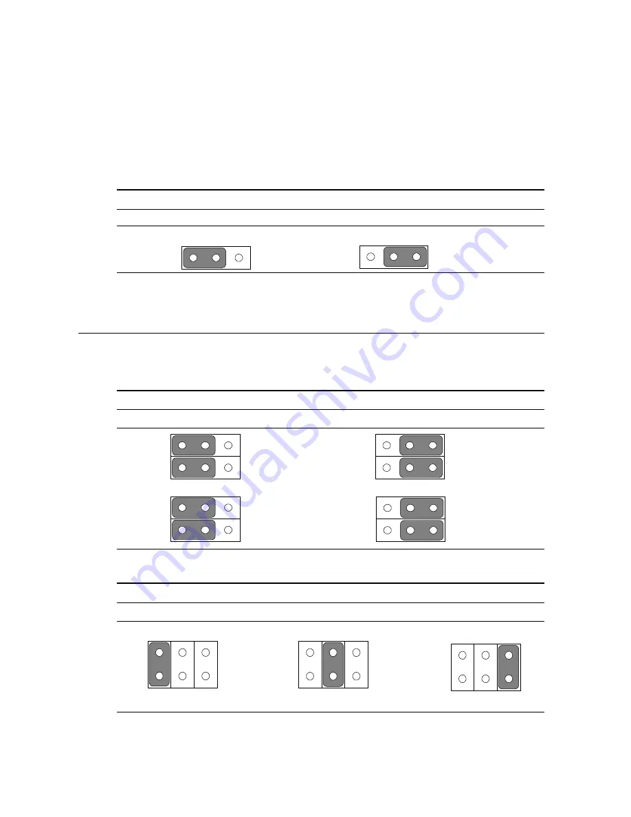
When the watchdog timer activates (i.e. CPU processing has come to a halt),
it can reset the system or generate an interrupt on IRQ11. This can be set via
jumper JP2 as shown below:

Table3-5: Watchdog activity selection (JP2)

System reset

IRQ11

* default setting

3.7

COM2 RS-232/422/485 setting (JP3, JP4,JP5)

COM2 can be configured to operate in RS-232/422/485 mode. This is done
via JP3,JP4,and JP5.

Table 3-6: COM2 RS-232/422/485 setting (JP3, JP4)

*RS-232

RS-422/485

JP4                                                 JP4

JP3                                                 JP3

* default setting

Table 3-7: COM2 RS-232/422/485 setting (JP5)

*RS-232

RS-422

RS-485

*default setting

2

4

6

2

4

6

2

4

6

3

1

5

2

4

6

1

3

5

2

4

6

1

3

5

1

6

2

5

1

6

2

5

5

1

6

2

5

1

6

2

Содержание PPC-A84

Страница 1: ...PPC A84 NS GXm processor based Panel PC with 8 4 LCD flat panel display User s Manual...

Страница 2: ...smitted in any form or by any means without the prior written permission of Advantech Co Ltd Information provided in this manual is intended to be accurate and reliable However Advantech Co Ltd assume...

Страница 3: ...in a particular installation If this equipment does cause harmful interference to radio or television reception which can be determined by turning the equipment off and on the user is encouraged to tr...

Страница 4: ...l FDD or IDE device 4 pin DC Power inlet cable 180 cm Assembly mounting screws Drivers and Utilities CD ROM disk Hard drive disk carrier and connector Male contact pin x 3 and female contact pin x 3 A...

Страница 5: ...tative or Advantech s customer service center for technical support if you need additional assistance Please have the following information ready before you call Product name and serial number Descrip...

Страница 6: ...ment should be noted 11 If the equipment is not used for a long time disconnect it from the power source to avoid damage by transient over voltage 12 Never open the equipment For safety reasons the eq...

Страница 7: ...it wird im Falle einer berspannung eine Besch digung vermieden 12 Durch die L ftungs ffnungen d rfen niemals Gegenst nde oder Fl ssigkeiten in das Ger t gelangen Dies k nnte einen Brand bzw elektrisch...

Страница 8: ...sal Mounting Arm Optional 11 Chapter 2 System Setup 13 2 1 A Quick Tour of the Panel PC 14 2 2 Preparing For First time Usage 19 2 3 Installation Procedures 19 2 3 1 Connecting the power inlet cable 1...

Страница 9: ...PC A84 PCM 5821 33 3 1 Introduction 34 3 2 Features 35 3 3 Jumpers and Connectors 36 3 3 1 Setting jumpers 36 3 3 2 Jumpers 37 3 3 3 Connectors 38 3 3 4 Locating jumpers and connectors 39 3 4 Wake on...

Страница 10: ...n 66 Chapter 6 Touchscreen 67 6 1 Introduction 68 6 1 1 General information 68 6 1 2 Specifications 68 6 2 Installation of Touchscreen Driver 68 6 2 1 Installation for MS DOS 69 6 2 2 Installation for...

Страница 11: ...sword Setting 102 8 12 IDE HDD Auto Detection 102 8 13 Save and Exit Setup 103 8 14 Exit Without Saving 103 Appendix A Programming the Watchdog Timer 105 A 1 Programming the Watchdog Timer 106 Appendi...

Страница 12: ...onnector CN8 124 C 11 Power Switch Connector CN10 125 C 12 Speaker and Microphone Connector CN20 125 C 13 Power Test Connector PS1 126 C 14 COM2 127 C 15 External IDE Connector 128 C 16 External Floop...

Страница 13: ...connector J3 119 Table C 4 Keyboard Connector J4 120 Table C 5 Internal Touchscreen Connector J5 121 Table C 6 CompactFlash Disk Secondary IDE Connector CN2 122 Table C 7 CD IN CN3 123 Table C 8 Powe...

Страница 14: ...5 Install or remove the power supply HDD drive PCACIA module 18 Figure 3 1 Locating jumpers and connectors PCM 5821 front side 39 Figure 3 2 Locating jumpers and connectors PCM 5821 rear side 40 Figur...

Страница 15: ...l Information This chapter gives background information on the PPC A84 Sections include Introduction Specifications Front View Dimensions Cutout Dimensions Panel Mounting Universal Mounting Arm C H A...

Страница 16: ...ing more flexibility in applications Die cast housing The completely sealed housing protects the system in tough harsh environments The die cast housing also acts as a heat sink to prevent the system...

Страница 17: ...e BIOS Award 256KB Flash memory support LCD brightness control intellectual cooling fan control PnP suspend to disk memory ACPI APM sub function boot ROM boot from CD ROM drive boot from LS 120 and ZI...

Страница 18: ...isplay type 18 bits TFT 8 4 Display Mode 64 gray scales 256 K colors Transmissive type Max resolution 800 x 600 Pixel size 0 213mm x 0 213 mm View angle 60 Luminance 120 cd m Temperature 0 50 C Simult...

Страница 19: ...consumption 5 V 200 mA Software driver Supports DOS WINDOWS 95 98 NT 4 0 Lifetime More than 3 million touches DC input power supply module 12volt or 24volt 12 V Pwr Supply 24 V Pwr Supply Input voltag...

Страница 20: ...ification revison 2 2 compliant Note The PCMCIA driver is an option which does not come with the PPC A84 system For more informa tion contact your local dealer or our sales represen tative Environment...

Страница 21: ...Chapter 1 General Information 7 1 3 Front View The front view of the PPC A84 is shown below Power Indicator Figure 1 1 Front view of the PPC A84...

Страница 22: ...8 PPC A84 User s Manual 1 4 Dimensions The PPC A84 can be placed on a shelf or a table or mounted into a panel Cutout panel dimensions are as follows Figure 1 2 Dimensions of the PPC A84...

Страница 23: ...ormation 9 1 5 Cutout Dimensions Suggestion The PPC A84 will stand on a shelf or a table or you can mount it into a panel Cutout panel dimensions are the following Figure 1 3 Dimensions of cutout and...

Страница 24: ...s in the accessory box To mount the PPC A84 into a panel 1 Removed the four caps from the front mask 2 Insert the screws from the front side into the holes and tighten then with the nuts in the back s...

Страница 25: ...installing the system Simply grasp the PPC A84 position it to remove glare adjust to the most comfortable viewing angle fix it with screws and everything is done Suspend mounting With the universal a...

Страница 26: ...ed convenient and ease access such as the warehousing and logistics Stand mounting The PPC A84 can be held on the movable stand for those applica tions with mobility and flexibility considerations suc...

Страница 27: ...of the Panel PC Preparing for First time Usage Installation Procedure Installing I O Equipment How to Install the software to HDD Running the BIOS Setup Program Installing the System Software Installi...

Страница 28: ...l PC take a moment to become familiar with the locations and purposes of the controls drives connectors and ports which are illustrated in the figures below When you place the panel PC upright on the...

Страница 29: ...System Setup 15 When you look at the top side of the panel PC you will see two door for DC power supply hard disk drive and PCMCIA expansion sockets as shown in Fig 2 2 Figure 2 2 Top side view of the...

Страница 30: ...tion is at the bottom of the panel PC as shown in Fig 2 3 and Fig 2 4 The I O section includes various I O ports including serial ports parallel port the Ethernet port USB ports the microphone jack an...

Страница 31: ...ial COM1 port b Serial COM2 port c PS 2 keyboard connector d mouse connector e Parallel port f VGA port g Ethernet port h USB port i Line in j Microphone in k Speaker out Figure 2 4 I O section of the...

Страница 32: ...upply HDD drive and PCMCIA module are removable and easy to change and maintain Figure2 5 Install or remove the power supply HDD drive and PCMCIA module DC24 V or 12V Power Supply plug in module for 2...

Страница 33: ...r CD ROM in the accessory box 4 pin power cable for external FDD or IDE device in the accessory box AT keyboard PS 2 or serial mouse for system software installation i e Microsoft Windows NT etc 2 3 I...

Страница 34: ...s of the power adaptor as well as to the frame ground cable Solder firmly STEP 2 Align the soldered pins and their cables with the corresponding polarization marks on the front part of the male insula...

Страница 35: ...21 STEP 4 Use the metal plate and the two screws to secure the cables to the bottom tray Please refer to the illustration above Bottom tray Metal plate STEP 3 Mount the front part of the male insulato...

Страница 36: ...84 User s Manual Upper cap STEP 5 Attach the upper cap to the bottom tray and secure it with the screws STEP 6 Now that you have completed the assembly of the male insulator plug it into the female in...

Страница 37: ...pin transfer connector and four pieces of M3x4 screws and two long screws for the 44 pin transfer connec tor in the accessory box 2 Connect the transfer connector to 2 5 HDD screw the two screws to fi...

Страница 38: ...ies to the system are switched Off 2 Slip the SODIMM into the socket at a 45 degree angle and carefully fit the bottom of the card against the connectors 3 Gently push the SODIMM into a perpendicular...

Страница 39: ...dc and 12 Vdc to both IDE device and FDD The following are instructions for installation 1 Adjust the jumper setting of your IDE device to be a slave IDE device 2 Unscrew the two attachment screws and...

Страница 40: ...mouse port on the PPC A84 is a PS 2 mouse port Note All But keyboard is the default setting 2 4 3 Mic in line in speaker out The PPPC A84 is equipped with a high quality audio interface which provide...

Страница 41: ...are turned off 2 Attach the interface cable of the serial device to the panel PC s serial port If necessary attach the other end of the interface cable to your serial device Fasten any retaining scre...

Страница 42: ...panel PC and then turn on the panel PC 5 If necessary run the panel PC s BIOS setup program to configure the parallel port to respond as required by your printer and software operating environment 2...

Страница 43: ...rew the two screws and detach the metal plate Attach a communication cable and a power cable to the FDD port then attach them to an FDD drive Insert a disk containing the software in FDD drive to proc...

Страница 44: ...stem Whenever you turn on the power the system reads the settings stored in CMOS RAM and compares them to the equipment check conducted during the power on self test POST If an error occurs an error m...

Страница 45: ...y the operating system files to it Refer to your operating system user s manual for instructions on partitioning and formatting a hard drive 2 8 Installing the Drivers After installing your system sof...

Страница 46: ...32 PPC A84 User s Manual...

Страница 47: ...The Engine of PPC A84 PCM 5821 Introduction Features Jumpers and Connectors Wake on LAN selction CMOS clear Watchdog timer configuration COM2 RS 232 422 485setting Buzzer enable C H A P T E R 3...

Страница 48: ...DB 9 connector as COM1 and a mini DIN PS 2 keyboard mouse interface An SVGA LCD display controller LCD and CRT displays allows LCD screen resolutions up to 1024 x 768 and CRT resolutions up to 1280 x...

Страница 49: ...128 MB system memory by SODIMM SDRAM On board VGA LCD controller On board 10 100Base T Ethernet interface Supports on board CompactFlash socket Built in Enhanced IDE AT bus hard disk drive interface...

Страница 50: ...will have three pins labeled 1 2 and 3 In this case you would connect either pins 1 and 2 or pins 2 and 3 The jumper settings are schematically depicted in this manual as follows A pair of needle nos...

Страница 51: ...gure your system to suit your applications The table below lists the function of each of the board jumpers Table 3 1 Jumpers and their functions Label Function JP1 Power type of Lan JP2 CMOS Clear and...

Страница 52: ...power connector J2 Flat panel display connector J3 Primary IDE hard drive connector J4 Keyboard connector J5 Internal touchscreen connector CN1 SODIMM socket CN2 Compact Flash Disk secondary IDE conn...

Страница 53: ...Cx5530 Buzzer enable JP10 Brightness VR JS2 Power Fan power connector CN6 Power type of Lan JP1 Primary IDE Connector J3 CD IN connector CN3 Power test connector PS1 CPU Fan power connector CN8 I O bo...

Страница 54: ...er and Microphone connector CN 20 Inverter Power Connector J1 Keyboard connector J4 COM2 RS 232 422 485 Setting JP3 JP4 JP5 External KBT2 CN7 Power Switch CN10 Flat Panel Display Connector J2 SODIMM s...

Страница 55: ...lways turn off the power supply before setting Clear CMOS Set the jumper back to Normal operation before turning on the power supply Table3 4 Clear CMOS External RTC JP2 Normal operation Clear CMOS de...

Страница 56: ...hdog activity selection JP2 System reset IRQ11 default setting 3 7 COM2 RS 232 422 485 setting JP3 JP4 JP5 COM2 can be configured to operate in RS 232 422 485 mode This is done via JP3 JP4 and JP5 Tab...

Страница 57: ...Chapter 3 The Engine of PPC A84T PCM 5821 43 3 8 Buzzer enable JP10 Table 3 8 Buzzer enable JP10 Enable Disable default setting...

Страница 58: ...44 PPC A84 User s Manual...

Страница 59: ...ce This chapter provides information on Ethernet configuration Introduction Installation of Ethernet Driver Installation for WINDOWS 95 Installation for WINDOWS 98 Installation for WINDOWS NT Further...

Страница 60: ...ombined with system BIOS which can be enabled disabled in the BIOS setup 4 2 Installation of Ethernet Driver Before installing the Ethernet driver note the procedures below You must know which operati...

Страница 61: ...el b a Press Have Disk button 1 2 3 4 Click Device Manager Other Devices item c Remove PCI Ethernet Controller item a Select Start Settings Control Panel and Network icon b Click Add button a Select t...

Страница 62: ...48 PPC A84 User s Manual a Select Realtek RTL8139 A B C b 8130 PCI Fast 6 a Click OK button 7 5 a Type the path D WIN95 LAN b Click OK button Ethernet Click OK button...

Страница 63: ...Chapter 4 PCI Bus Ethernet Interface 49 a Press Yes to start computer 9 END 8 a Insert Win95 CD to load related files b Click OK button...

Страница 64: ...nel b system 1 Click Device Manager Other Devices item c Highlight PCI Ethernet Controller item and then click properties button folder and then update Driver button to update Ethernet driver a Choose...

Страница 65: ...Ethernet Interface 51 6 7 a Highlight Network adapters and then click next 5 8 button a Click Have Disk button a Click the OK button to take the highlighted item a Type D Win98 LAN to install driver a...

Страница 66: ...52 PPC A84 User s Manual 10 11 9 a Click Finish button to complete a Click Next button installation a Click Yes button to reboot system END...

Страница 67: ...ick Network icon b Choose the Adapters label c Click the Add button 2 a Press Have Disk button 3 a Insert the Drivers and Utilities CD ROM b Fill the path D WINNT LAN c Press the OK button 4 a Choose...

Страница 68: ...table RTL8139 Duplex mode for your application b Click OK button 6 a Finish network configuration and then click the OK button 7 a Press Yes button to restart your computer end a Finish network config...

Страница 69: ...Chapter 4 PCI Bus Ethernet Interface 55 4 3 Further Information Realtek web site www realtek com tw Advantech web site www advantech com www advantech com tw...

Страница 70: ...56 PPC A84 User s Manual...

Страница 71: ...5 PCI SVGA Setup Introduction Installation of SVGA Driver Installation for WINDOWS 95 Installation for WINDOWS 98 Installation for WINDOWS NT Further Information C H A P T E R...

Страница 72: ...le frequency multisync monitors are handled as if they were analog monitors 5 1 2 Display memory With 2 4 MB share memory the VGA controller can drive CRT displays or color panel displays with resolut...

Страница 73: ...ustrations are examples only You must follow the flow chart instructions and pay attention to the instructions which then appear on your screen Note2 The CD ROM drive is disgnated as D throughout this...

Страница 74: ...95 a Select Start Settings Control Panel Display Settings b Press Advanced Properties a Choose the Adapter label b Press the Change button a Press the Have Disk button a Insert the utility disc into...

Страница 75: ...Setup 61 a Select the highlighted Control Panel item b Click the OK a Cyrix Xpress Graphics TM appears in the a Press the close button a Press Yes to 5 6 7 8 button adapter label b Click the Apply and...

Страница 76: ...er s Manual 5 2 2 Installation for WINDOWS 98 4 Take default setting Typical 2 Press Finish button 3 Press Next button to take default setting 1 a Select Start Run b Type D win98 Vga Audio Cyrixmed ex...

Страница 77: ...llation 5 Following the instruction to insert Windows 98 CD ROM END Note A common driver for Windows98 is used on both SVGA and Audio While installing the SVGA driver for Windows98 as seen in the abov...

Страница 78: ...nsert the disc into the CD ROM driver b Type D WINNT VGANT c Press the OK button 2 Press Change button 3 Click the Have Disk button 1 a Select Start Settings Control Panel b Double click the Display i...

Страница 79: ...5 6 Press Yes to process 5 a Select the hightlighted item b Press the OK button END a Press OK to reboot a Repeat Step 1 in this manual b Adjust resolution and color c Click Test to see the result d C...

Страница 80: ...rther information about the PCI SVGA and audio installation in your PPC A84 including driver updates troubleshooting guides and FAQ lists visit the following web resources NS web site www nsc com Adva...

Страница 81: ...6 Touchscreen Introduction Installation of Touchscreen Driver Installation for DOS Installation for WINDOWS 95 Installation for WINDOWS 98 Installation for WINDOWS NT C H A P T E R...

Страница 82: ...contains a native 32 bit driver designed for Windows 95 98 and a 32 bit control panel program for the PPC A84 system To facilitate the installation of the touchscreen driver you should read the instr...

Страница 83: ...DOS RONICSTOUCH 2 Type the command Install C Enter Installing system software automatically creates a directory named TSR411 PS2 in C drive 3 Change the directory to C TSR411 PS2 4 Type M in the direc...

Страница 84: ...S 95 a Insert the c Type the path a Click OK a Click OK 1 2 3 4 Drivers and Utilities CD b Click Start button and and then Run button a Press Install Now button to install touchscreen driver button to...

Страница 85: ...Chapter 6 Touchscreen 71 a Click touchscreen 5 6 Control Panel version R411 PS2 icon to enable the Touchscreen Control Panel a Press Calibration button to calibrate the touchscreen END...

Страница 86: ...en Run c Type the path D win98 Ronicstouch WIN setup exe a Press Ok button a Click Install Now button a Click Yes button to restart your computer 6 2 3 Installation for WINDOWS 98 a Insert the Drivers...

Страница 87: ...Chapter 6 Touchscreen 73 5 a Touch targets to calibrate the touchscreen controller END a Press Calibration button to calibrate the touchscreen END...

Страница 88: ...en Run c Type the path D win98 Ronicstouch WIN setup exe a Press Ok button a Click Install Now button a Click Yes button to restart your computer 6 2 4 Installation for WINDOWS NT a Insert the Drivers...

Страница 89: ...Chapter 6 Touchscreen 75 5 a Touch targets to calibrate the touchscreen controller END a Press Calibration button to calibrate the touchscreen...

Страница 90: ...76 PPC A84 User s Manual...

Страница 91: ...7 Audio Setup Introduction Installation of Audio Driver Installation for WINDOWS 95 Installation for WINDOWS 98 Installation for WINDOWS NT Further Information C H A P T E R...

Страница 92: ...ynthesizer is register compatible with the OPL3 and has extended capabili ties 7 2 Installation of Audio Driver Before installing the audio driver please take note of the procedures detailed below You...

Страница 93: ...items PCI Multimedia Audio Device and Unknown Device folder of Device a Select No and then click 1 2 3 4 a Choose sound video Manager b Click close button to escape Device Manager a Click Add new hard...

Страница 94: ...User s Manual a Press Have Disk 5 6 7 8 a Click finish button button a Click Add new hardware icon then next b Type the path D WIN95 Audio c Click OK button a Select Xpress Audio TM 16 bit sound b Pre...

Страница 95: ...Chapter 5 PCI SVGA Audio Setup 81 9 10 a Press Yes button to start your computer a Insert Win95 CD to load related files b Click OK button END...

Страница 96: ...ser s Manual 7 2 2 Installation for WINDOWS 98 4 Take default setting Typical 2 Press Finish button 3 Press Next button to take default setting 1 a Select Start Run b Type D win98 Vga Audio Cyrixmed e...

Страница 97: ...ete installation 5 Following the instruction to insert Windows 98 CD ROM END Note A common driver for WINDOWS 98 is used on both SVGA and Audio Once you install the SVGA driver for WINDOWS 98 as Chapt...

Страница 98: ...al 1 a Select Start Settings Control Panel b Double click Multimedia icon 3 a Choose Unlisted or Updated Driver item b Click the OK button 2 a Select the Devices item b Click the Add button 7 2 3 Inst...

Страница 99: ...ton 4 a Insert Drivers and Utilities CD ROM b Type the path D winnt audiont c Click OK button 6 a Press the Restart Now button to reboot your computer a Select the highlighted item b Press the Ok butt...

Страница 100: ...ter END 7 3 Further Information For further information about the audio installation in your PPC A84 including driver updates troubleshooting guides and FAQ lists visit the following web resources NS...

Страница 101: ...8 Award BIOS Setup This chapter describes how to set BIOS configuration data C H A P T E R...

Страница 102: ...ngs according to your system configuration Some setup items will not be explained because it is recommended that users do not change such items Note Values for the various setup items that appear on y...

Страница 103: ...utility screen will appear as shown in Fig 8 1 Use the arrow keys to select and press Enter to run the selected program 8 3 Standard CMOS Setup Figure 8 2 CMOS setup screen The standard CMOS setup sc...

Страница 104: ...OMP PRECOMP PRECOMP PRECOMP PRECOMP The cylinder number at which the disk drive changes the write timing LANDZ LANDZ LANDZ LANDZ LANDZ The cylinder number where the disk drive heads read write are sea...

Страница 105: ...ystem should have been fine tuned before shipping Improper setup may cause the system to fail so consult your dealer before making any changes V V V V Virus W irus W irus W irus W irus War ar ar ar ar...

Страница 106: ...Floppy Seek Boot Up Floppy Seek Boot Up Floppy Seek Boot Up Floppy Seek Boot Up Floppy Seek When enabled assigns the BIOS to perform floppy disk drive tests by issuing seek commands Note that such te...

Страница 107: ...tions are Disabled Default Enabled OS Select For DRAM 64MB OS Select For DRAM 64MB OS Select For DRAM 64MB OS Select For DRAM 64MB OS Select For DRAM 64MB If your operating system OS is OS2 select OS2...

Страница 108: ...oller USB Legency Support oller USB Legency Support When enabled the USB devices are activated The options are Disabled Default Enabled Build in CPU Audio Build in CPU Audio Build in CPU Audio Build...

Страница 109: ...s are 1 5M Default 2 5M Flat Panel Status Flat Panel Status Flat Panel Status Flat Panel Status Flat Panel Status The system will support 18 bit TFT LCD signal output because this option is designed a...

Страница 110: ...25 33 3 50 75 IRQ Activity IRQ Activity IRQ Activity IRQ Activity IRQ Activity After the time period which you set in the Suspend Mode feature elapses the system advances from Doze Mode to Suspend Mod...

Страница 111: ...ary 8 7 PNP PCI Configuration Setup Figure 8 6 PNP PCI configuration setup screen Resour Resour Resour Resour Resources Contr ces Contr ces Contr ces Contr ces Controlled By olled By olled By olled By...

Страница 112: ...a The options are Disabled Default Enabled PCI IRQ Activated By PCI IRQ Activated By PCI IRQ Activated By PCI IRQ Activated By PCI IRQ Activated By If your IDE card is triggered by edge set it at Edge...

Страница 113: ...es of the system parameters that allow minimum system performance 8 9 Load Setup Defaults Selecting this field loads the factory defaults for BIOS and Chipset Features The system will automatically de...

Страница 114: ...ws the BIOS to tell the controller what it wants and then let the controller and the CPU perform the task by themselves Your system supports five modes numbered from 0 through 4 which differ primarily...

Страница 115: ...enabled the infrared receptor is activated The options are Disabled Default Enabled Onboar Onboar Onboar Onboar Onboard Parallel Port d Parallel Port d Parallel Port d Parallel Port d Parallel Port I...

Страница 116: ...on field and the Supervisor Password is enabled you will be prompted for the supervisor password every time you try to enter the CMOS Setup utility If System is selected and User Password is enabled y...

Страница 117: ...ss Esc again or move the cursor to Exit Without Saving and press Y to retain the setup settings The following message will appear at the center of the screen to allow you to save data to CMOS and exit...

Страница 118: ...104 PPC A84T User s Manual...

Страница 119: ...4 is equipped with a watch dog timer that resets the CPU or generates an interrupt if processing comes to a standstill for any reason This feature ensures system reliability in industrial standalone o...

Страница 120: ...The value range is from 01 hex to 3E hex and the related time interval is from 1 sec to 62 sec Data Time Interval 01 1 sec 02 2 sec 03 3 sec 04 4 sec 3E 62 sec After data entry your program must refre...

Страница 121: ...H443 data REM Start and restart the watchdog 30 GOSUB 1000 REM Your application task 1 40 OUT H443 data REM Reset the timer 50 GOSUB 2000 REM Your application task 2 60 OUT H443 data REM Reset the ti...

Страница 122: ...108...

Страница 123: ...Full Disassembly Procedures A P P E N D I X B...

Страница 124: ...D cover plate and two screws on slot plate remove both the HDD FDD cover and slot plates then carefully detach the riser board with either a screwdriver or pliers 2 Unscrew the eight hexagonal and two...

Страница 125: ...pendix C Full Disassembly Procedures 111 Figure B 1 Disassembly steps 1 4 Step 1 Step 2 Step 3 Step 4 HDD FDD cover plate I O bracket HDD FDD slot plat I O Board Back cover CPU board bracket Riser Boa...

Страница 126: ...rol board and touchscreen control board bracket then remove both components 6 Detach the inverter by unscrewing the screw located on the right corner of the inverter 7 Unscrew the rest of the screws o...

Страница 127: ...Appendix C Full Disassembly Procedures 113 Figure B 2 Disassembly steps 5 7 CPU board bracket Inverter Motherboard Touchscreen control board bracket Touchscreen control board Step 5 Step 6 and Step 7...

Страница 128: ...touchscreen is stuck on the LCD holding plate by a strongly double side adhesive tape We do not recommend you to remove it unless the touchscreen is detective and you would like to replace it Note Be...

Страница 129: ...Appendix C Full Disassembly Procedures 115 Figure B 3 Disassembly steps 8 12 Step 8 Step 12 Step 9 Step 11 Step 10 LCD cabinet LCD LCD holding plate Touchscreen Front bezel...

Страница 130: ...116 PPC 123 User s Manual...

Страница 131: ...CompactFlash Disk Secondary IDE Connector CN2 CD IN CN3 Power Fan Power Connector CN6 External KBT2 CN7 CPU Power Fan Connector CN8 Power Switch Connector CN10 Speaker and Microphone Connector CN20 P...

Страница 132: ...VBR 5 Vcc C 2 Flat Panel Display Connector J2 Table C 2 Flat panel display connector J2 Pin Signal Pin Signal 1 VDDSAFE5 2 VDDSAFE5 3 GND 4 GND 5 VDDSAFE3 6 VDDSAFE3 7 Vcon 8 GND 9 NC 10 NC 11 P0 12 P...

Страница 133: ...ctor J3 4 44 43 3 42 41 1 2 Table C 3 Primary IDE connector J3 Pin Signal Pin Signal 1 IDE RESET 2 GND 3 DATA 7 4 DATA 8 5 DATA 6 6 DATA 9 7 DATA 5 8 DATA 10 9 DATA 4 10 DATA 11 11 DATA 3 12 DATA 12 1...

Страница 134: ...1 34 N C 35 ADDR 0 36 ADDR 2 37 HDD SELECT 0 38 HDD SELECT 1 39 IDE ACTIVE 0 40 GND 41 VCC 42 VCC 43 GND 44 N C low active C 4 Keyboard Connector J4 Table C 4 Keyboard Connector J4 Pin Signal 1 VCC 2...

Страница 135: ...ternal Touchscreen Connector J5 Table C 5 Internal Touchscreen Connector J5 Pin Signal 1 DCD4 2 DSR4 3 RX4B 4 RTS4 5 TX4 6 CTS4 7 DTR4 8 R14 9 GND 10 GND 11 PC_MSDAT 12 EXT_MSDAT 13 PC_MSCLK 14 EXT_MS...

Страница 136: ...Signal 1 GND 26 GND 2 DATA3 27 DATA11 3 DATA4 28 DATA12 4 DATA5 29 DATA13 5 DATA6 30 DATA14 6 DATA7 31 DATA15 7 CS0S 32 CS1S 8 NC 33 NC 9 GND 34 IIOR1 10 NC 35 IIOW1 11 NC 36 GND 12 NC 37 IIRQ15 13 V...

Страница 137: ...DATA2 48 DATA9 24 NC 49 DATA10 25 GND 50 GND C 7 CD IN CN3 Table C 7 CD IN CN3 Pin Signal 1 CD_INR 2 CD_GND 3 CD_INL 4 CD_GND 1 2 4 3 C 8 Power Fan Power Connector CN4 Table C 8 Power Fan Power Connec...

Страница 138: ...ernal KBT2 Connector CN7 Table C 9 CPU Fan Power Connector CN7 Pin Signal 1 VCC 2 EXT_KBDAT2 3 EXT_KBCKL2 4 GND 1 2 4 3 C 10 CPU Fan Power Connector CN8 Table C 10 CPU fan power connector FAN1 Pin Sig...

Страница 139: ...N10 Table C 11 Power Switch Connector CN10 Pin Signal 1 VCC 2 GND 3 SUS_LED 4 FPRST 5 FPSW 6 FPSLP C 12 Speaker and Microphone Connector CN20 Table C 12 Speaker and Microphone Connector CN20 Pin Signa...

Страница 140: ...onnector PS1 4 20 19 3 18 17 1 2 Table C 13 Power Test Connector PS1 Pin Signal Pin Signal 1 VCC 3ATX 11 VCC 3ATX 2 VCC 3ATX 12 12 V 3 GND 13 GND 4 VCC 14 PSON 5 GND 15 GND 6 VCC 16 GND 7 GND 17 GND 8...

Страница 141: ...Appendix D Pin Assignments 127 C 14 COM2 1 5 9 6 3 2 4 7 8 Table C 14 COM2 Pin Signal RS 232 RS 422 RS 485 1 DCD TX DATA 2 RX TX DATA 3 TX RX 4 DTR RX 5 GND GND 6 DSR 7 RTS 8 CTS 9 RI...

Страница 142: ...7 DATA5 8 DATA10 9 DATA4 10 DATA11 11 DATA3 12 DATA12 13 DATA2 14 DATA13 15 DATA1 16 DATA14 17 DATA0 18 DATA15 19 SIGNAL GND 20 N C 21 HDD 0 22 GND 23 IO WRITE 24 GND 25 IO READ 26 GND 27 HD READY 28...

Страница 143: ...ELECT 3 GND 4 N C 5 GND 6 DRIVE TYPE 7 GND 8 INDEX 9 GND 10 MOTOR 0 11 GND 12 DRIVE SELECT 1 13 GND 14 DRIVE SELECT 0 15 GND 16 MOTOR 1 17 GND 18 DIRECTION 19 GND 20 STEP 21 GND 22 WRITE DATA 23 GND 2...

Страница 144: ...e Hex Device 000 01F DMA controller 020 021 Interrupt controller 1 master 022 023 Chipset address 040 05F 8254 timer 060 06F 8042 keyboard Controller 070 07F Real time clock non maskable interrupt NMI...

Страница 145: ...360 36F Reserved 378 37F Parallel printer port 1 LPT 2 380 38F SDLC bisynchronous 2 3A0 3AF Bisynchronous 1 3B0 3BF Monochrome display and printer adapter LPT1 3C0 3CF Reserved 3D0 3DF Color graphics...

Страница 146: ...132 PPC A84 User s Manual...

Отзывы: