background image

PCI-1727U User Manual

12

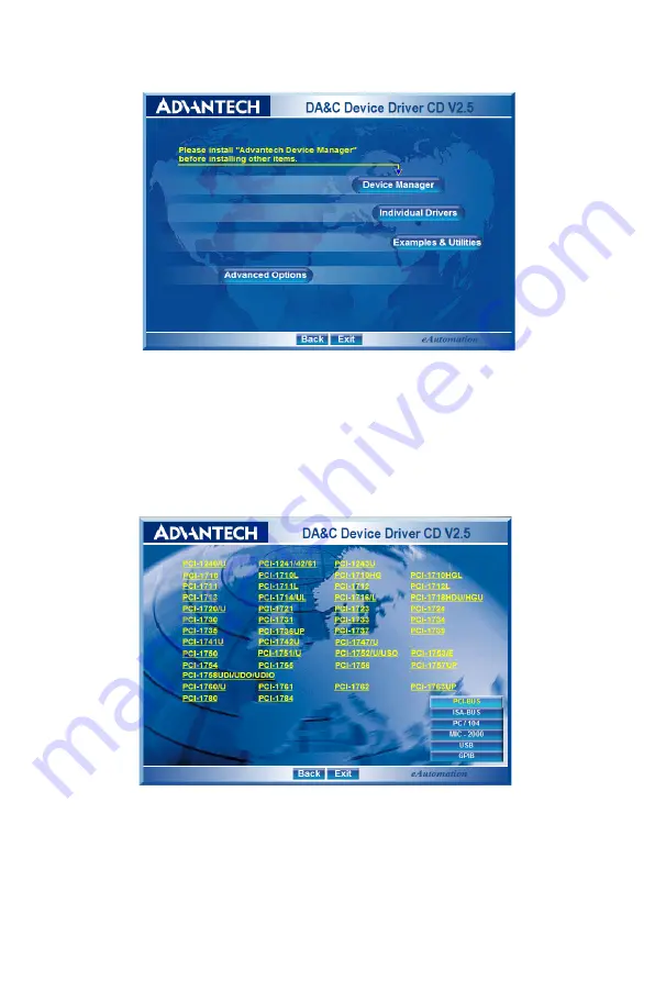
Figure 2.1:  Advantech Automation Software Setup

3. First, install the Advantech Device Manager.
4. Select the "

Individual Drivers

" to install the specific device driver 

then just follow the installation instructions step by step to complete 
your device driver installation and setup.

Figure 2.2: Different Options for Driver Setup

For further information on driver-related issues, an online version of the 
Device Drivers Manual is available by accessing the following path:

Start/Advantech Automation/Device Manager/Device Driver’s Manual

Содержание PCI-1727U

Страница 1: ...URE ASSET SOLUTIONS SERVICE CENTER REPAIRS Experienced engineers and technicians on staff at our full service in house repair center WE BUY USED E Sell your exce We also offer www artisan REMOTE INSPECTION Remotely inspect equipment before purchasing with our interactive website at www instraview com LOOKING FOR M Visit us on the information o specifications Contact us 888 88 SOURCE sales artisant...

Страница 2: ...PCI 1727U 12 ch Analog Output Card with Universal PCI User Manual ...

Страница 3: ...vantech Co Ltd Information provided in this manual is intended to be accurate and reli able However Advantech Co Ltd assumes no responsibility for its use nor for any infringements of the rights of third parties which may result from its use Acknowledgements PC LabCard is a trademark of Advantech Co Ltd IBM PC are trademarks of International Business Machines Corporation MS DOS Windows Microsoft V...

Страница 4: ...placement materials service time and freight Please consult your dealer for more details If you think you have a defective product follow these steps 1 Collect all the information about the problem encountered For example CPU speed Advantech products used other hardware and software used etc Note anything abnormal and list any onscreen messages you get when the problem occurs 2 Call your dealer an...

Страница 5: ...ot installed and used in accordance with the instruction manual may cause harmful interference to radio communications Opera tion of this equipment in a residential area is likely to cause harmful inter ference in which case the user will be required to correct the interference at his own expense Technical Support and Assistance Step 1 Visit the Advantech web site at www advantech com support wher...

Страница 6: ...t step on it Do not place anything over the power cord 10 All cautions and warnings on the equipment should be noted 11 If the equipment is not used for a long time disconnect it from the power source to avoid damage by transient overvoltage 12 Never pour any liquid into an opening This may cause fire or elec trical shock 13 Never open the equipment For safety reasons the equipment should be opene...

Страница 7: ...R This set of instructions is given according to IEC 704 1 Advantech disclaims all responsibility for the accuracy of any statements contained herein Safety Precaution Static Electricity Follow these simple precautions to protect yourself from harm and the products from damage 1 To avoid electrical shock always disconnect the power from your PC chassis before you work on it Don t touch any compone...

Страница 8: ...0 2 2 Driver Installation 11 Figure 2 1 Advantech Automation Software Setup 12 Figure 2 2 Different Options for Driver Setup 12 2 3 Hardware Installation 13 2 4 Device Configuration 14 Figure 2 3 The Device Manager Dialog Box 14 Figure 2 4 The Device Setting Dialog Box 15 Figure 2 5 Analog Output Test Utility 15 Chapter 3 Signal Connections 18 3 1 Overview 18 3 2 Switch Jumper Settings 18 Figure 3...

Страница 9: ...PCI 1727U User Manual viii ...

Страница 10: ...on the PCI 1727U and instruction on card con figuration in order to match your appli cation and prepare it for installation on your system Sections include Features Applications Installations Guide Software Overview Device Driver Programming Roadmap Accessories ...

Страница 11: ... 16 TTL DO channels that are easily applied with industrial on off control applications 1 1 Features 12 Analog output channels 14 bit resolution Multiple voltage output ranges 10V output and 0 20mA current loop sink 16 digital input and 16 digital output channelsTTL compatible Board ID Calibration Retain the latest analog digital output value after system reset The Advantech PCI 1727U offers the f...

Страница 12: ...cards have been installed on the same PC chassis With correct BoardID settings you can easily identify and access each card during hardware configuration and software programming 1 2 Applications Process control Programmable voltage source Programmable current sink Servo control Multiple loop PID control 1 3 Installation Guide Before you install your PCI 1727U card please make sure you have the fo...

Страница 13: ...y software packages After you get the necessary components and maybe some of the accesso ries for enhanced operation of your multifunction card you can then begin the installation procedure Figure 1 1 provides a concise flow chart to give users a broad picture of the software and hardware installation procedures Figure 1 1 Installation Flow Chart ...

Страница 14: ...tra charge It also comes with all Advantech DA C cards Advantech s Device Drivers features a complete I O function library to help boost your application performance Advantech Device Drivers for Win 2000 XP works seamlessly with development tools such as Visual C Visual Basic Borland C Builder and Borland Delphi Register level Programming Register level programming is available for experienced pro...

Страница 15: ...how to begin programming in each development tool Advantech offers a Tutorial Chapter in the Device Drivers Manual for your reference Please refer to the corresponding sections in this chapter on the Device Drivers Manual to begin your programming efforts You can also look at the example source code provided for each programming tool since they can get you very well oriented The Device Drivers Man...

Страница 16: ...the error code to DRV_GetErrorMessage function to return the error message Alternatively you can refer to the Device Drivers Error Codes Appendix in the Device Drivers Manual for a detailed listing of Error Codes Error IDs and the Error Messages 1 6 Accessories Advantech offers a complete set of accessory products to support the PCI 1727U card These accessories include 1 6 1 Wiring Cables PCL 1013...

Страница 17: ...b cards and allows easy yet reliable access to individual pin connec tions for the PCI 1727U card PCLD 880 The PCLD 880 is a universal screw terminal board compatible with any of the PC LabCards which have 37 pin D type connectors All the specifications connectors pin assignments and registry formats are the same Users can upgrade their system to PCI bus without changing any existing wiring system...

Страница 18: ...on This chapter contains a package item checklist proper instructions for unpacking and step by step procedures for card installation Sections include Unpacking Driver Installation Hardware Installation Device Configuration ...

Страница 19: ...l part of your computer chassis with your hand to dis charge the static electricity accumulated on your body Alternatively one can also use a grounding strap Touch the anti static bag to a metal part of your computer chassis before opening the bag Take hold of the card only by the metal bracket when removing it out of the bag After taking out the card you should first Inspect the card for any poss...

Страница 20: ...ed with your DA C card package Please follow the steps below to install the driver software 1 Insert the companion CD ROM into your CD ROM drive 2 The Setup program will be launched automatically if you have the autoplay function enabled on your system When the Setup Program is launched the Setup Screen will appear Note Keep the anti static bag for future use You might need the original bag to sto...

Страница 21: ...vice driver then just follow the installation instructions step by step to complete your device driver installation and setup Figure 2 2 Different Options for Driver Setup For further information on driver related issues an online version of the Device Drivers Manual is available by accessing the following path Start Advantech Automation Device Manager Device Driver s Manual ...

Страница 22: ...e of your computer to neutralize the static electricity that might be on your body 5 Insert the PCI 1727U card into a PCI slot Hold the card only by its edges and carefully align it with the slot Insert the card firmly into place 6 Fasten the bracket of the PCI card on the back panel rail of the com puter with screws 7 Connect appropriate accessories 50 pin flat cable wiring terminals etc if neces...

Страница 23: ...dvantech Device Drivers Setting Up the Device 1 To configure the I O device for your card you must first run the setup program by accessing Start Advantech Automation Device Manager Advantech Device Manager 2 You can then view the device s already installed on your system Please click the Setup button to configure your device Figure 2 3 The Device Manager Dialog Box 3 On the Device Setting dialog ...

Страница 24: ...and configured you can click the Test button to test your hardware by using the testing utility Figure 2 5 Analog Output Test Utility For more detailed information please refer to Chapter 2 of the Device Drivers Manual You can also find rich examples on the CD ROM to speed up your programming ...

Страница 25: ...PCI 1727U User Manual 16 ...

Страница 26: ...Signal Connections This chapter provides useful informa tion about how to connect input and output signals to the PCI 1727U via the I O connector Sections include Overview Switch Jumper Settings Signal Connections ...

Страница 27: ...o connect input and output signals to the PCI 1727U via the I O connector 3 2 Switch Jumper Settings The PCI 1727U card has two function jumper settings Figure 3 1 Card Connectors Jumpers Switches Location Descriptiom CN1 IDC 20 pin connector for digital output channels CN2 IDC 20 pin connector for digital input channels CN3 DSub 37 pin connector for analog output channels JP1 Keep the latest outp...

Страница 28: ...r Name Function Description JP1 Retain last status after hot reset Default configuration Table 3 2 Summary of Jumper Settings Jumper Switch Setting Function Description JP2 JP5 Set AO channels to VOLTAGE MODE SW2 JP2 JP5 Set AO channels to CURRENT MODE SW2 ...

Страница 29: ...ors All connectors accommodate the same type of flat cable or can be connected to 37 pin D type connectors through our PCLD 880 indus trial wiring kit The following figures detail the pin assignments for each connector BD3 BD2 BD1 BD0 Board ID 1 1 1 1 0 1 1 1 0 1 1 1 0 1 2 1 1 0 0 3 1 0 1 1 4 1 0 1 0 5 1 0 0 1 6 1 0 0 0 7 0 1 1 1 8 0 1 1 0 9 0 1 0 1 10 0 1 0 0 11 0 0 1 1 12 0 0 1 0 13 0 0 0 1 14 0...

Страница 30: ...21 Chapter3 Connector 1 CN1 Digital Output Connector 2 CN2 Digital Input ...

Страница 31: ...PCI 1727U User Manual 22 Connector 3 CN3 D A output ...

Страница 32: ...elow PCI 1727U Side External Side Table 3 3 I O Connection Signal Description Signal Ref Direction Description DO 0 15 DGND Output Digital output channel 0 15 DI 0 15 DGND Input Digital input channel 0 15 AO 0 15 V I AGND Output Analog input channel 0 15 V stands for voltage out put I stands for current loop Voltage output and current loop share the same pin at AO8 9 10 11 selectable by jumpers 5V...

Страница 33: ...rcuit consists of a power FET and a constant current source The voltage bias of this current output should be within 8 to 36 V to insure correct operation An external 24 V power supply is ideal for this application The PCI 1727U also provides an internal 12 V power source for current loops should this be required There are three ways of connecting the load 1 Grounded load with a floating supply 2 ...

Страница 34: ... I O levels are TTL compatible To transmit or receive digital sig nals to and from other TTL devices the connection should be as follows When the PCI 1727U is used to detect an OPEN SHORT signal from a switch or relay a pull up resistor must be added to ensure the input is tied to a high 5 V when the contact is open The following diagram shows this configuration ...

Страница 35: ...ata acquisition system Avoid running cables through any conduit that may contain power lines If it is necessary to place a signal cable parallel to a power line with a high voltage or current try to keep a safe distance between them Place the signal cable at a right angle to the power line to minimize the effect If the cable travels through an area with significant electromagnetic inter ference su...

Страница 36: ...2 APPENDIX A Specifications ...

Страница 37: ...nt in Vulgate output 15mA max Throughput Software Static Update Setting time 70µs Power on default value all output range is 0V or 0mA in power on Fuse on each channel 0 1A Digital Input Channel 16 channel Level TTL compatible Logic0 0 8V max Logic1 2 0V min Input loading 0 5V 0 4mA max low 2 7V 50µA max high Digital Output Channel 16 channel Level TTL compatible Logic0 0 5V 8mA sink Logic1 2 4V 0...

Страница 38: ...500mA max 12V 150 mA typical 300mA max 12V 100 mA typical 130mA max General Connector 37 pin D type female Dimension 175 100mm 6 9 3 9 Operation temperature 0 50 C 32 149 F Storage temperature 20 60C 40 185 F Related humidity 5 95 non condensing ...

Страница 39: ...PCI 1727U User Manual 30 ...

Страница 40: ...2 APPENDIX B Block Diagram ...

Страница 41: ...am PC I BU S PCI BRI DGE D A 0 Vout I out D A 1 Vout I out D A 2 Vout I out D A 3 Vout I out D A 4 Vout I out D A 5 Vout I out D A 6 Vout I out D A 7 Vout I out D A 8 Vout I out D A 9 Vout I out D A 10 Vout I out D A 11 Vout I out D I 15 0 D O 15 0 ...

Страница 42: ...URE ASSET SOLUTIONS SERVICE CENTER REPAIRS Experienced engineers and technicians on staff at our full service in house repair center WE BUY USED E Sell your exce We also offer www artisan REMOTE INSPECTION Remotely inspect equipment before purchasing with our interactive website at www instraview com LOOKING FOR M Visit us on the information o specifications Contact us 888 88 SOURCE sales artisant...

Отзывы: