15
ITA-2000 User Manual
/ 用户手册
Chapter 2
H
/W Installation
硬件安装
2.4.6
CAN Connector
/
CAN 接口
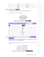
ITA-2000 provides CAN Bus Interface by two D-sub 9-pin connector.
ITA-2000 提供 2 个 D-sub 9 针 CAN 总线接口。
Figure 2.12 D-sub COM Connector
/D-sub COM 接口
2.4.7
Power ON/OFF Button / Power Input Connector
/
电源开关按钮/
电源输入接口
ITA-2000 comes with a Power ON/OFF button and AC inlet, its support AT function
with that carries 110 V ~ 240 VAC power input.
ITA-2000 带有电源开关按钮和 AC 插座,支持 AT 功能,具有 110 V
~
240 VAC 电源输
入功能。
Figure 2.13 Power button and AC inlet
/ 电源按钮和 AC 插座
6
DI_4
DI_5
7
DI_5
DI_6
8
DI_6
DI_7
9
DI_7
DI_8
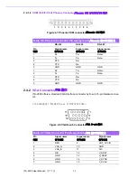
Table 2.12: CAN Connector Pin Assignments
/CAN 接口针脚定义
Pin
针脚
Signal name
信号名称
1
NC
2
CAN_L
3
GND
4
NC
5
NC
6
NC
7
CAN_H
8
NC
9
NC
Содержание ITA-2000
Страница 8: ...ITA 2000 User Manual viii...
Страница 12: ...ITA 2000 User Manual xii...
Страница 13: ...Chapter 1 1 General Information This chapter provides general informnation about the ITA 2000 ITA 2000...
Страница 16: ...ITA 2000 User Manual 4 1 5 Dimension Diagram Figure 1 1 Dimension diagram...
Страница 17: ...Chapter 2 2 H W Installation This chapter provides H W Instal lation about the ITA 2000 ITA 2000...
Страница 28: ...ITA 2000 User Manual 16...
Страница 29: ...Chapter 3 3 BIOS Operation BIOS This chapter describes how to set BIOS configuration data BIOS...
Страница 60: ...ITA 2000 User Manual 48...
Страница 61: ...Chapter 5 5 System Setup This chapter introduces the instal lation process...
Страница 67: ...Appendix A A Programming the Watchdog Timer...
Страница 79: ...Appendix B B Examples of the CAN Transfer tool CAN...


